Cirkit Designer
Your all-in-one circuit design IDE
Home /
Project Documentation
ESP32-Based Drone with GPS, Camera, and MPU-6050 for Surveillance
Circuit Documentation
Summary
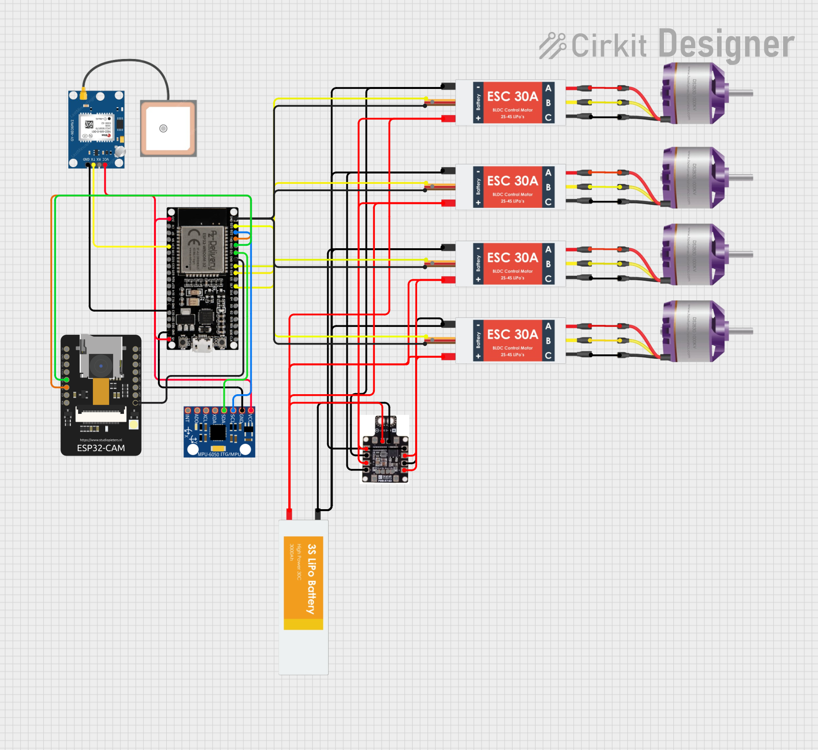
This document provides a detailed overview of a drone surveillance system. The system includes multiple brushless motors controlled by Electronic Speed Controllers (ESCs), an MPU-6050 for motion sensing, a GPS module for location tracking, and an ESP32 microcontroller for overall control. Additionally, an ESP32-CAM is used for capturing images, and a PDB XT60 is used for power distribution. The system is powered by a LiPo battery.
Component List
Brushless Motor
- Description: A motor that operates without brushes, commonly used in drones for its efficiency and reliability.
- Pins: L1, L2, L3
Electronic Speed Controller (ESC)
- Description: A device that controls the speed of the brushless motor by varying the power supplied to it.
- Pins: Battery VCC, Battery GND, Signal, 5v out, GND out, M1, M2, M3
MPU-6050
- Description: A 6-axis motion tracking device that includes a 3-axis gyroscope and a 3-axis accelerometer.
- Pins: VCC, GND, SCL, SDA, XDA, XCL, AD0, INT
PDB XT60
- Description: A Power Distribution Board used to distribute power from the battery to various components.
- Pins: +, -, GND, VCC, 5V, 12V
LiPo Battery
- Description: A Lithium Polymer battery used to power the entire system.
- Pins: VCC, GND
GPS NEO 6M
- Description: A GPS module used for location tracking.
- Pins: VCC, RX, TX, GND
ESP32 38 PINS
- Description: A microcontroller with built-in WiFi and Bluetooth capabilities, used for controlling various components.
- Pins: GND, G23, G22, TXD, RXD, G21, G19, G18, G5, G17, G16, G4, G0, G2, G15, SDI, SD0, CLK, 3V3, EN, SP, SN, G34, G35, G32, 33, G25, G26, G27, G14, G12, G13, SD2, SD3, 5V
ESP32-CAM
- Description: A camera module based on the ESP32 microcontroller, used for capturing images.
- Pins: 5V, GND, IO12, IO13, IO15, IO14, IO2, IO4, VOT, VOR, VCC, IO0, IO16, 3V3
Wiring Details
Brushless Motor
- L1 connected to M1 of ESC
- L2 connected to M2 of ESC
- L3 connected to M3 of ESC
Electronic Speed Controller (ESC)
- Battery VCC connected to + of PDB XT60
- Battery GND connected to - of PDB XT60
- Signal connected to G17 of ESP32 38 PINS
- GND out connected to GND of ESP32 38 PINS
- M1 connected to L1 of Brushless Motor
- M2 connected to L2 of Brushless Motor
- M3 connected to L3 of Brushless Motor
MPU-6050
- VCC connected to 3V3 of ESP32 38 PINS
- GND connected to GND of ESP32 38 PINS
- SCL connected to G22 of ESP32 38 PINS
- SDA connected to G21 of ESP32 38 PINS
PDB XT60
- + connected to Battery VCC of ESC
- - connected to Battery GND of ESC
- VCC connected to VCC of LiPo Battery
- GND connected to GND of LiPo Battery
LiPo Battery
- VCC connected to VCC of PDB XT60
- GND connected to GND of PDB XT60
GPS NEO 6M
- VCC connected to 5V of ESP32 38 PINS
- TX connected to G34 of ESP32 38 PINS
- GND connected to GND of ESP32 38 PINS
ESP32 38 PINS
- G17 connected to Signal of ESC
- GND connected to GND out of ESC
- G22 connected to SCL of MPU-6050
- G21 connected to SDA of MPU-6050
- 5V connected to VCC of GPS NEO 6M
- G34 connected to TX of GPS NEO 6M
- TXD connected to IO14 of ESP32-CAM
- RXD connected to IO15 of ESP32-CAM
- GND connected to GND of ESP32-CAM
ESP32-CAM
- 5V connected to 5V of ESP32 38 PINS
- GND connected to GND of ESP32 38 PINS
- IO14 connected to TXD of ESP32 38 PINS
- IO15 connected to RXD of ESP32 38 PINS
Documented Code
Code for ESC Microcontroller
void setup() {
  // put your setup code here, to run once:

}

void loop() {
  // put your main code here, to run repeatedly:

}
Code for MPU-6050 Microcontroller
#include <Wire.h>
#include <Adafruit_MPU6050.h>
#include <Adafruit_Sensor.h>
#include <TinyGPS++.h>
#include <HardwareSerial.h>

// Define pins for HC-SR04
const int trigPin = 12;  // Change this to your trig pin
const int echoPin = 13;  // Change this to your echo pin

// Define pins for MPU6050
Adafruit_MPU6050 mpu;

// Define pins for GPS
HardwareSerial mySerial(1); // Use UART1 for GPS
TinyGPSPlus gps;

void setup() {
    // Start serial communication
    Serial.begin(115200);

    // Initialize HC-SR04
    pinMode(trigPin, OUTPUT);
    pinMode(echoPin, INPUT);

    // Initialize MPU6050
    if (!mpu.begin()) {
        Serial.println("Failed to find MPU6050 chip");
        while (1) {
            delay(10);
        }
    }

    // Initialize GPS
    mySerial.begin(9600, SERIAL_8N1, 16, 17); // Adjust RX, TX pins for GPS
}

void loop() {
    // HC-SR04 Distance Measurement
    digitalWrite(trigPin, LOW);
    delayMicroseconds(2);
    digitalWrite(trigPin, HIGH);
    delayMicroseconds(10);
    digitalWrite(trigPin, LOW);

    long duration = pulseIn(echoPin, HIGH);
    float distance = (duration * 0.034) / 2; // Calculate distance in cm
    Serial.print("Distance: ");
    Serial.print(distance);
    Serial.println(" cm");

    // Read from MPU6050
    sensors_event_t a, g, temp;
    mpu.getEvent(&a, &g, &temp);
    Serial.print("Accel X: "); Serial.print(a.acceleration.x); Serial.print(" m/s^2");
    Serial.print(" | Accel Y: "); Serial.print(a.acceleration.y); Serial.print(" m/s^2");
    Serial.print(" | Accel Z: "); Serial.print(a.acceleration.z); Serial.print(" m/s^2");
    Serial.println();

    // Read from GPS
    while (mySerial.available() > 0) {
        gps.encode(mySerial.read());
        if (gps.location.isUpdated()) {
            Serial.print("Latitude= "); Serial.print(gps.location.lat(), 6);
            Serial.print(" Longitude= "); Serial.print(gps.location.lng(), 6);
            Serial.println();
        }
    }

    delay(1000); // Delay for readability
}
Code for GPS NEO 6M Microcontroller
/*
 * Development of Drone Surveillance Technology Using ESP32
 * This code interfaces with an ESP32, MPU-6050, GPS NEO 6M, and ESP32-CAM.
 * The ESP32 reads data from the MPU-6050 (IMU), and GPS.
 * It also controls the ESCs for the brushless motors and captures images using the ESP32-CAM.
 */

#include <Wire.h>
#include <Adafruit_MPU6050.h>
#include <Adafruit_Sensor.h>
#include <WiFi.h>
#include <ESP32Servo.h>

// Pin Definitions