
ESP32-Controlled RFID Access System with LCD Feedback and Visual Indicators
View and Edit Project In Cirkit Designer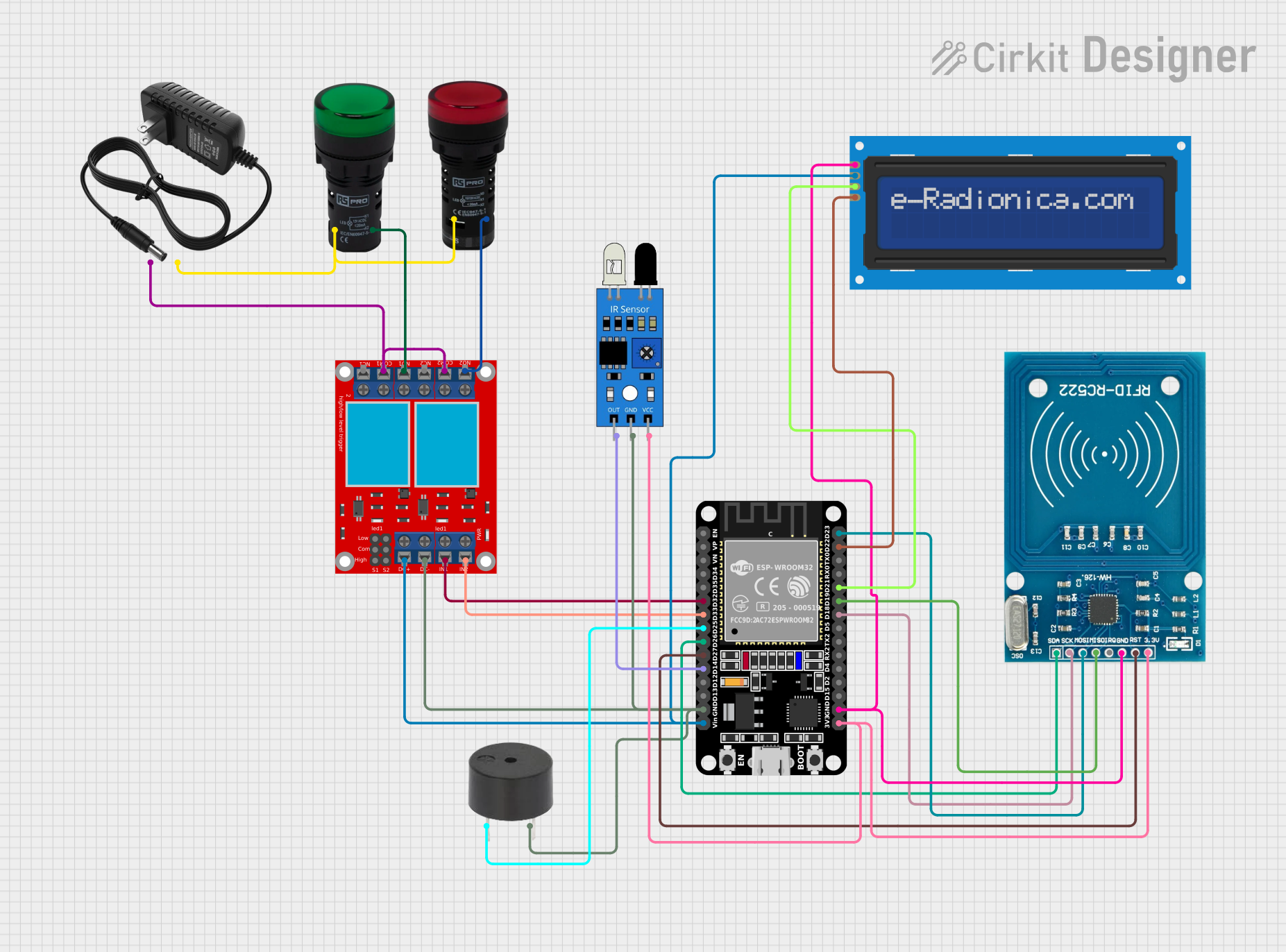
Circuit Documentation
Summary
This circuit integrates various components to perform a set of functions centered around an ESP32 microcontroller. The ESP32 controls an RFID-RC522 module for RFID reading, an LCD screen for display, a 2-channel relay module for switching high-power devices, a buzzer for audio signaling, and IR sensor for proximity detection, and pilot lamps for visual status indication. The circuit is powered by a 12V power supply, with voltage regulation for the ESP32 and other 3.3V components.
Component List
ESP32 (30 pin)
- Description: A microcontroller with Wi-Fi and Bluetooth capabilities.
- Pins: EN, VP, VN, D34, D35, D32, D33, D25, D26, D27, D14, D12, D13, GND, Vin, D23, D22, TX0, RX0, D21, D19, D18, D5, TX2, RX2, D4, D2, D15, 3V3
RFID-RC522
- Description: An RFID reader module for reading RFID tags.
- Pins: VCC (3.3V), RST, GND, IRQ, MISO, MOSI, SCK, SDA
LCD screen 16x2 I2C
- Description: A 16x2 character LCD display with an I2C interface.
- Pins: SCL, SDA, VCC, GND
Pilot Lamp Red
- Description: A red indicator lamp.
- Pins: X1, X2
2 channel relay module
- Description: A module with two relays for controlling high-power devices.
- Pins: N.O. 2, COM 2, N.C. 2, N.O. 1, COM 1, N.C. 1, pin 7, pin 8, pin 9, pin 10, pin 11, pin 12, VCC+, VCC- (GND), IN 1, IN 2
Pilot Lamp Green
- Description: A green indicator lamp.
- Pins: X1, X2
12v power supply
- Description: A power supply providing 12V output.
- Pins: +, -
IR sensor
- Description: An infrared sensor for detecting proximity.
- Pins: out, gnd, vcc
Buzzer
- Description: An audio signaling device.
- Pins: PIN, GND
Wiring Details
ESP32 (30 pin)
- D32 connected to 2 channel relay module IN 1
- D33 connected to 2 channel relay module IN 2
- D25 connected to buzzer PIN
- D26 connected to RFID-RC522 SDA
- D27 connected to RFID-RC522 RST
- D14 connected to IR sensor out
- GND connected to common ground
- Vin connected to LCD screen 16x2 I2C VCC and 2 channel relay module VCC+
- D23 connected to RFID-RC522 MOSI
- D22 connected to LCD screen 16x2 I2C SCL
- D21 connected to LCD screen 16x2 I2C SDA
- D19 connected to RFID-RC522 MISO
- D18 connected to RFID-RC522 SCK
- 3V3 connected to RFID-RC522 VCC (3.3V) and IR sensor vcc
RFID-RC522
- SDA connected to ESP32 D26
- RST connected to ESP32 D27
- GND connected to common ground
- MOSI connected to ESP32 D23
- MISO connected to ESP32 D19
- SCK connected to ESP32 D18
- VCC (3.3V) connected to ESP32 3V3
LCD screen 16x2 I2C
- SCL connected to ESP32 D22
- SDA connected to ESP32 D21
- VCC connected to ESP32 Vin
- GND connected to common ground
Pilot Lamp Red
- X1 connected to 12v power supply -
- X2 connected to 2 channel relay module N.O. 2
2 channel relay module
- IN 1 connected to ESP32 D32
- IN 2 connected to ESP32 D33
- VCC+ connected to ESP32 Vin
- VCC- (GND) connected to common ground
- N.O. 2 connected to Pilot Lamp Red X2
- COM 2 connected to 12v power supply +
- COM 1 connected to 12v power supply +
- N.O. 1 connected to Pilot Lamp Green X2
Pilot Lamp Green
- X1 connected to 12v power supply -
- X2 connected to 2 channel relay module N.O. 1
IR sensor
- out connected to ESP32 D14
- gnd connected to common ground
- vcc connected to ESP32 3V3
Buzzer
- PIN connected to ESP32 D25
- GND connected to common ground
Documented Code
No code has been provided for the microcontrollers in the circuit. The code would typically include initialization and control logic for the RFID reader, LCD display, relay module, buzzer, and IR sensor, as well as handling communication protocols such as I2C for the LCD and SPI for the RFID reader. It would also manage the state of the pilot lamps based on the system status or external inputs.