
ESP32-Based GPS and GSM Tracking System with Vibration Detection and Alerts
View and Edit Project In Cirkit Designer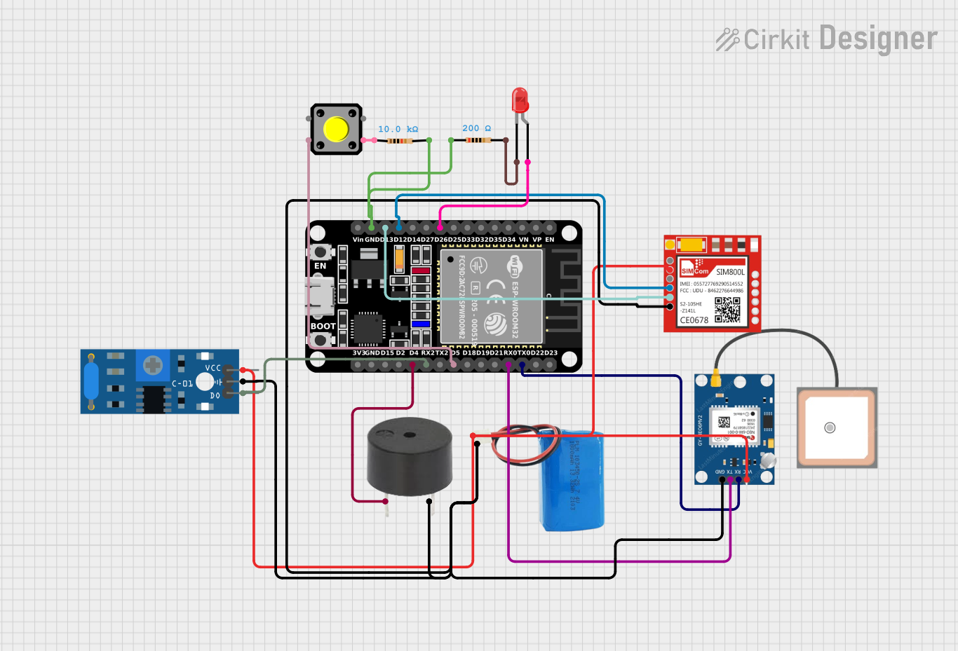
Circuit Documentation
Summary
This circuit integrates various components to perform a set of functions centered around the ESP32 microcontroller. The ESP32 serves as the central processing unit, interfacing with a GPS module (NEO 6M), a GSM module (Sim800l), a vibration sensor (SW-420), a pushbutton, a buzzer, and an LED. The circuit is powered by a 5V battery, and it includes resistors for current limiting and pull-down configurations. The ESP32 facilitates communication with the GPS and GSM modules via serial connections and monitors the state of the vibration sensor and pushbutton. The buzzer and LED provide audio and visual feedback, respectively.
Component List
ESP32 (30 pin)
- Microcontroller with WiFi and Bluetooth capabilities.
- 30 GPIO pins including analog inputs, digital inputs/outputs, UART, I2C, and SPI.
SW-420 Vibration Sensor
- Detects vibrations and outputs a digital signal.
Buzzer
- Emits an audible tone when powered.
Pushbutton
- A momentary switch that closes the circuit when pressed.
LED: Two Pin (red)
- A red light-emitting diode that illuminates when forward-biased.
GPS NEO 6M
- A GPS module that provides location data.
5v Battery
- Provides the power supply for the circuit.
Sim800l
- A GSM/GPRS module for cellular communication.
Resistor (10k Ohms)
- A resistor with a resistance of 10,000 Ohms.
Resistor (200 Ohms)
- A resistor with a resistance of 200 Ohms.
Wiring Details
ESP32 (30 pin)
D26connected to the anode of the LED.D12connected to the RXD pin of the Sim800l.D13connected to the TXD pin of the Sim800l.GNDconnected to one end of a 10k Ohm resistor.TX0connected to the RX pin of the GPS NEO 6M.RX0connected to the TX pin of the GPS NEO 6M.D5connected to Pin 1 of the Pushbutton.RX2connected to the Digital output of the SW-420 Vibration Sensor.D4connected to the PIN of the buzzer.
SW-420 Vibration Sensor
vccconnected to the positive terminal of the 5v battery.Groundconnected to the negative terminal of the 5v battery.Digital outputconnected toRX2on the ESP32.
Buzzer
PINconnected toD4on the ESP32.GNDconnected to the negative terminal of the 5v battery.
Pushbutton
Pin 1connected toD5on the ESP32.Pin 2connected to one end of a 200 Ohm resistor.
LED: Two Pin (red)
anodeconnected toD26on the ESP32.cathodeconnected to one end of a 200 Ohm resistor.
GPS NEO 6M
VCCconnected to the positive terminal of the 5v battery.RXconnected toTX0on the ESP32.TXconnected toRX0on the ESP32.GNDconnected to the negative terminal of the 5v battery.
5v Battery
positiveterminal connected toVCCon the SW-420 Vibration Sensor, Sim800l, and GPS NEO 6M.negativeterminal connected toGroundon the SW-420 Vibration Sensor,GNDon the Sim800l, buzzer, and GPS NEO 6M.
Sim800l
VCCconnected to the positive terminal of the 5v battery.RXDconnected toD12on the ESP32.TXDconnected toD13on the ESP32.GNDconnected to the negative terminal of the 5v battery.
Resistor (10k Ohms)
- One end connected to
GNDon the ESP32. - The other end connected to the negative terminal of the 5v battery (common ground).
Resistor (200 Ohms)
- One end connected to
Pin 2of the Pushbutton. - The other end connected to the cathode of the LED.
Documented Code
There is no code provided for the microcontroller in this circuit. The functionality of the ESP32 in this circuit would typically involve reading inputs from the GPS module, vibration sensor, and pushbutton, controlling the buzzer and LED, and communicating with the GSM module. The code would be responsible for initializing the peripherals, handling interrupts or polling for sensor states, and implementing communication protocols for the GPS and GSM modules.