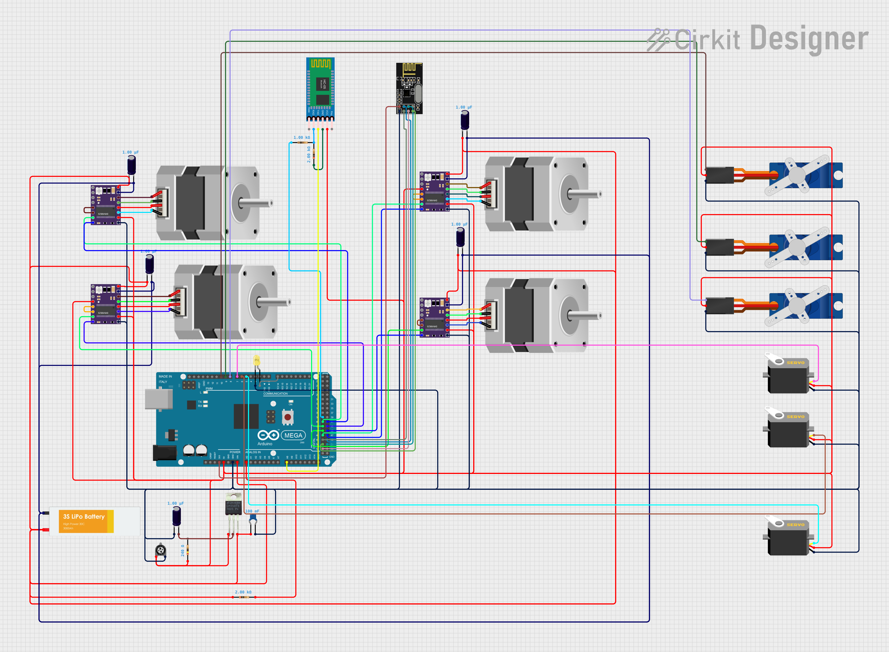
Arduino Mega 2560-Controlled Robotic System with Wireless Communication

Circuit Documentation
Summary
This circuit is designed to control a system that includes stepper motors, servos, and wireless communication modules. It is powered by a Lipo battery and regulated by an LM340T5 7805 voltage regulator. The control logic is managed by an Arduino Mega 2560, which interfaces with DRV8825 stepper motor drivers, servo motors, an HC-05 Bluetooth module, and an NRF24L01 wireless module. The circuit also includes various capacitors and resistors for stability and current limiting, as well as a trimmer potentiometer for adjustable resistance.
Component List
Electrolytic Capacitors
- Electrolytic Capacitor - Used for smoothing voltage fluctuations. Capacitance: 1 µF.
Stepper Motors
- Stepper Motor (Bipolar) - Used for precise motion control in applications such as robotics and CNC machines.
DRV8825 Stepper Motor Drivers
- DRV 8825 - A motor driver that controls the stepper motors. It has multiple control pins for step, direction, and micro-stepping configurations.
Power Supply
- Lipo Battery - Provides the power source for the circuit.
Voltage Regulator
- LM340T5 7805 - A voltage regulator that outputs a stable 5V from a higher voltage input.
Trimmer Potentiometer
- Trimmer Potentiometer - An adjustable resistor with a resistance of 10 kΩ.
Resistors
- Resistor - Used for current limiting and voltage division. Resistances: 240 Ω, 2 kΩ, 1 kΩ.
Ceramic Capacitor
- Ceramic Capacitor - Used for decoupling and noise reduction on power lines. Capacitance: 0.1 F.
Microcontroller
- Arduino Mega 2560 - The main controller for the circuit, with numerous I/O pins for interfacing with various components.
Servos
- Servo - An actuator that can be precisely controlled for angular positioning.
- Tower Pro SG90 servo - A small and lightweight servo motor for precise control.
Wireless Communication Modules
- HC-05 Bluetooth Module - Enables wireless communication via Bluetooth.
- NRF24L01 - A wireless transceiver module for short-range RF communication.
LED
- LED: Two Pin (yellow) - A yellow LED used as an indicator light.
Wiring Details
Electrolytic Capacitors
- Connected across power supply lines for voltage smoothing.
Stepper Motors
- Connected to DRV8825 drivers for control.
DRV8825 Stepper Motor Drivers
- EN, M0, M1, M2, RST, SLP, STEP, DIR, VMOT, GND MOTOR, B2, B1, A1, A2, FAULT, GND LOGIC pins are used for motor control and interfacing with the Arduino Mega 2560.
Power Supply
- Lipo Battery provides power to the circuit.
Voltage Regulator
- LM340T5 7805 regulates the input voltage to a stable 5V output.
Trimmer Potentiometer
- Adjustable resistance connected as required in the circuit.
Resistors
- Used in various parts of the circuit for current limiting and voltage division.
Ceramic Capacitor
- Placed close to power supply pins of ICs for noise reduction.
Microcontroller
- Arduino Mega 2560 controls the logic of the circuit and interfaces with all other components.
Servos
- Controlled by PWM signals from the Arduino Mega 2560.
Wireless Communication Modules
- HC-05 Bluetooth Module and NRF24L01 are used for wireless communication and are interfaced with the Arduino Mega 2560.
LED
- Connected to an I/O pin of the Arduino Mega 2560 for indication purposes.
Documented Code
Arduino Mega 2560 Code (sketch.ino)
void setup() {
  // put your setup code here, to run once:

}

void loop() {
  // put your main code here, to run repeatedly:

}
This code is a template for the Arduino Mega 2560. The setup() function runs once when the microcontroller is powered on or reset. The loop() function runs repeatedly, allowing the microcontroller to perform its tasks. The actual implementation details will depend on the specific requirements of the circuit's application.