
Arduino UNO and ESP32 CAM-based Interactive Device with Display and Sensors
View and Edit Project In Cirkit Designer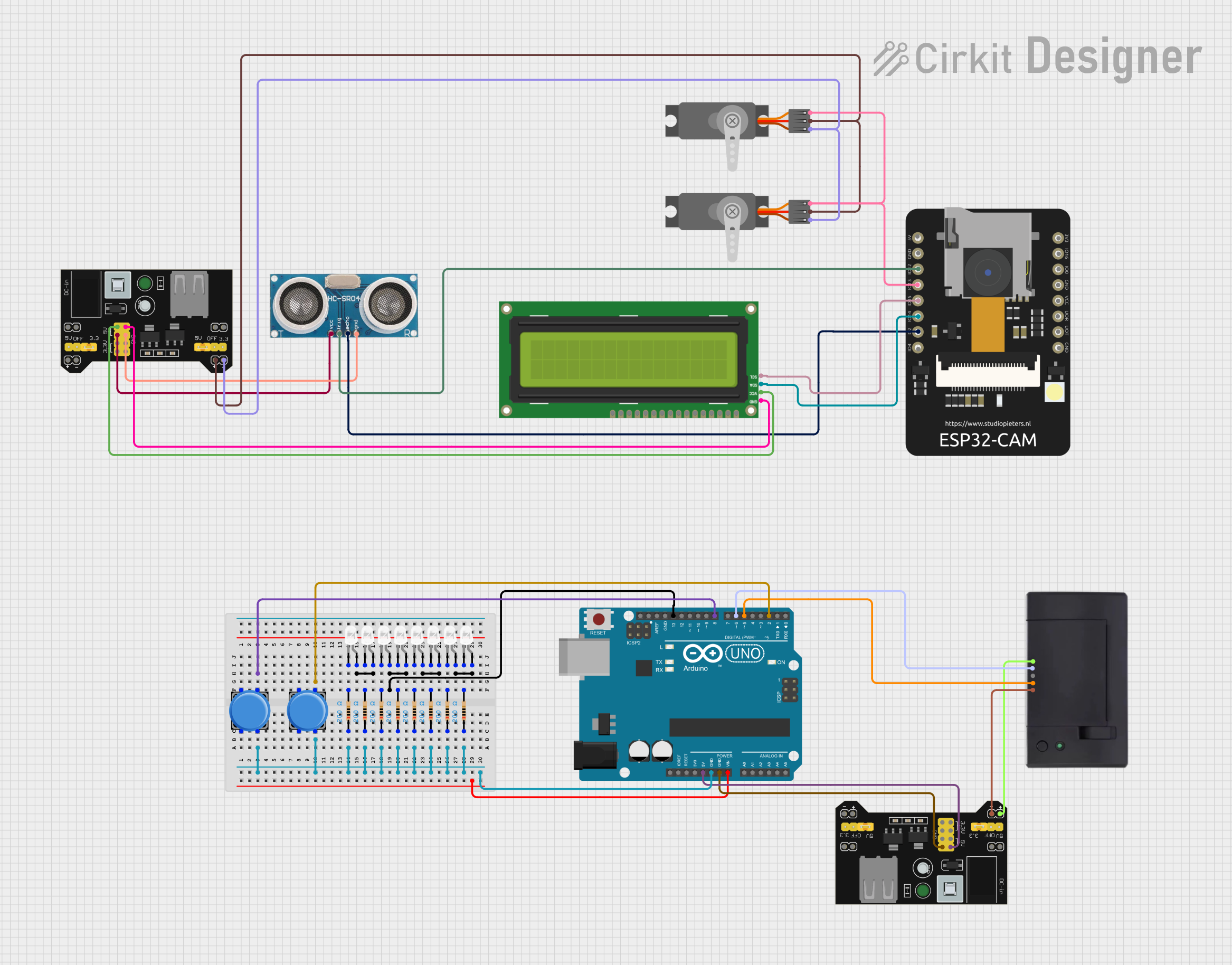
Circuit Documentation
Summary
This document provides a detailed overview of a circuit that includes a variety of components such as an I2C LCD 16x2 Screen, an Arduino UNO microcontroller, an Ultrasonic Sensor, Pushbuttons, Servos, LEDs, Resistors, a Breadboard Power Supply Module, a TTL serial converter, and an ESP32 CAM module. The circuit is designed to interface with various sensors and actuators, and it includes user input through pushbuttons and visual feedback through LEDs and an LCD screen. The Arduino UNO serves as the primary controller, while the ESP32 CAM adds advanced features such as Wi-Fi connectivity and camera functionality.
Component List
- I2C LCD 16x2 Screen: A display screen that uses the I2C communication protocol.
- Arduino UNO: A microcontroller board based on the ATmega328P, widely used for prototyping and educational purposes.
- Ultrasonic Sensor: A sensor that measures distance by emitting ultrasonic waves and measuring the time taken for the echo to return.
- Pushbutton: A simple switch mechanism for controlling some aspect of a machine or a process.
- Servo (Wokwi Compatible): An actuator that allows for precise control of angular or linear position, velocity, and acceleration.
- LED: Two Pin (white): A basic light-emitting diode that emits white light when powered.
- Resistor: A passive two-terminal electrical component that implements electrical resistance as a circuit element.
- MB102 Breadboard Power Supply Module 3.3V/5V: A power supply module that provides both 3.3V and 5V outputs for breadboard projects.
- ttl: A TTL serial converter used for serial communication.
- ESP32 CAM: A small-sized camera module with Wi-Fi capabilities.
Wiring Details
I2C LCD 16x2 Screen
- SCL: Connected to ESP32 CAM GPIO15
- SDA: Connected to ESP32 CAM GPIO14
- VCC (5V): Connected to MB102 Breadboard Power Supply Module 5V
- GND: Connected to MB102 Breadboard Power Supply Module GND
Arduino UNO
- GND: Common ground with Pushbuttons, Resistors, and MB102 Breadboard Power Supply Module
- D8: Connected to Pushbutton Pin 3
- D2: Connected to another Pushbutton Pin 3
- D13: Connected to the anodes of two LEDs
- Vin: Not connected
- 5V: Connected to MB102 Breadboard Power Supply Module 5V
- D6: Connected to ttl DTR
- D5: Connected to ttl RX
Ultrasonic Sensor
- +VCC: Connected to MB102 Breadboard Power Supply Module 5V
- Trigger: Connected to ESP32 CAM GPIO12
- Echo: Connected to ESP32 CAM GPIO2
- GND: Connected to MB102 Breadboard Power Supply Module GND
Pushbuttons
- Pin 4: Common ground with Resistors and Arduino UNO GND
- Pin 3: One connected to Arduino UNO D8, another to D2
Servos (Wokwi Compatible)
- V+: Connected to MB102 Breadboard Power Supply Module VCC
- GND: Connected to MB102 Breadboard Power Supply Module GND
- PWM: Connected to ESP32 CAM GPIO13
LEDs: Two Pin (white)
- Anode: Connected to Arduino UNO D13 or other LEDs
- Cathode: Connected to individual Resistors
Resistors
- Pin 1: Common ground with Pushbuttons and Arduino UNO GND
- Pin 2: Connected to individual LED cathodes
MB102 Breadboard Power Supply Module 3.3V/5V
- VCC: Connected to Servos V+ and ttl VCC
- GND: Common ground with various components
- 3.3V: Not connected
- 5V: Connected to I2C LCD 16x2 Screen VCC (5V), Ultrasonic Sensor +VCC, Arduino UNO 5V
ttl
- DTR: Connected to Arduino UNO D6
- RX: Connected to Arduino UNO D5
- TX: Not connected
- VCC: Connected to MB102 Breadboard Power Supply Module VCC
- GND: Connected to MB102 Breadboard Power Supply Module GND
ESP32 CAM
- GPIO15: Connected to I2C LCD 16x2 Screen SCL
- GPIO14: Connected to I2C LCD 16x2 Screen SDA
- GPIO12: Connected to Ultrasonic Sensor Trigger
- GPIO13: Connected to Servos PWM
- GPIO2: Connected to Ultrasonic Sensor Echo
Documented Code
Arduino UNO Code (sketch.ino)
void setup() {
  // put your setup code here, to run once:

}

void loop() {
  // put your main code here, to run repeatedly:

}
Note: The provided code for the Arduino UNO is a template with empty setup and loop functions. This code needs to be populated with the logic to control the circuit components based on the desired functionality.