
Arduino UNO Based Environmental Monitoring System with LoRa Communication
View and Edit Project In Cirkit Designer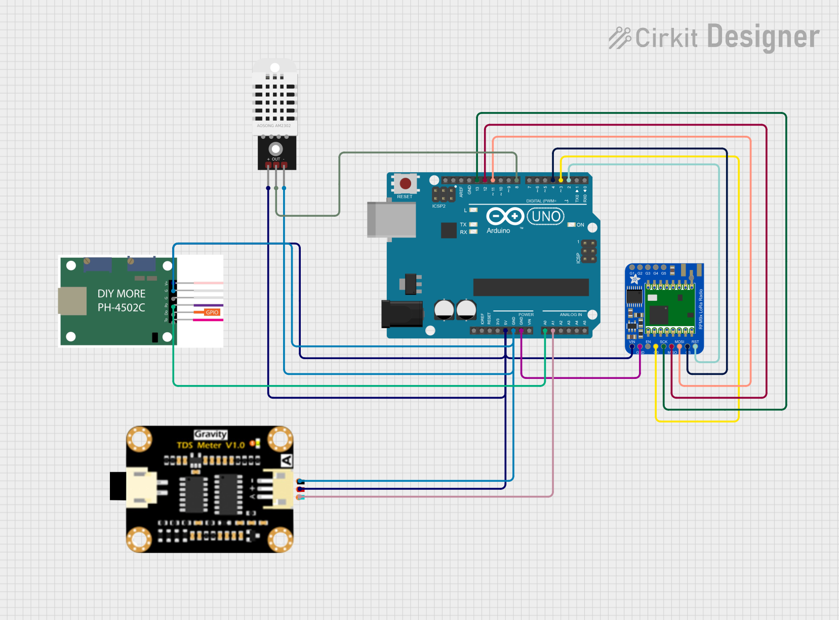
Circuit Documentation
Summary
This circuit integrates an Arduino UNO with various sensors and modules to perform a range of functions. The Arduino UNO serves as the central processing unit, interfacing with a DHT22 temperature and humidity sensor, a ph4502c pH sensor module, a TDS (Total Dissolved Solids) sensor module, and an Adafruit RFM9x LoRa Radio for wireless communication. The circuit is designed to monitor environmental parameters and communicate data wirelessly, suitable for applications such as weather stations, smart agriculture, or water quality monitoring systems.
Component List
Arduino UNO
- Microcontroller board based on the ATmega328P
- Features digital I/O pins, analog input pins, and various power pins
Adafruit RFM9x LoRa Radio
- A long-range wireless communication module
- Operates in the sub-GHz frequency bands
- Features several digital I/O pins for interfacing
DHT22
- A digital temperature and humidity sensor
- Provides calibrated digital output
ph4502c
- A pH sensor module
- Outputs both analog and digital signals
TDS Sensor Module
- Measures the Total Dissolved Solids in water
- Provides an analog output
Wiring Details
Arduino UNO
- 5V: Powers the ph4502c, Adafruit RFM9x LoRa Radio, TDS Sensor Module, and DHT22
- GND: Common ground for ph4502c, Adafruit RFM9x LoRa Radio, TDS Sensor Module, and DHT22
- A0: Receives the analog output from the ph4502c
- A1: Receives the analog output from the TDS Sensor Module
- D13 (SCK): Serial Clock for Adafruit RFM9x LoRa Radio
- D12 (MISO): Master In Slave Out for Adafruit RFM9x LoRa Radio
- D11 (MOSI): Master Out Slave In for Adafruit RFM9x LoRa Radio
- D8: Digital input from the DHT22 sensor
- D4 (CS): Chip Select for Adafruit RFM9x LoRa Radio
- D3 (DIO0): Digital I/O pin 0 for Adafruit RFM9x LoRa Radio
- D2 (RST): Reset for Adafruit RFM9x LoRa Radio
Adafruit RFM9x LoRa Radio
- VIN: Connected to 5V from Arduino UNO
- GND: Connected to GND on Arduino UNO
- SCK, MISO, MOSI, CS, DIO0, RST: Connected to corresponding pins on Arduino UNO
DHT22
- +: Connected to 5V from Arduino UNO
- Out: Connected to D8 on Arduino UNO
- -: Connected to GND on Arduino UNO
ph4502c
- VCC: Connected to 5V from Arduino UNO
- G1: Connected to GND on Arduino UNO
- Po: Connected to A0 on Arduino UNO
TDS Sensor Module
- TDS Positive: Connected to 5V from Arduino UNO
- TDS Negative: Connected to GND on Arduino UNO
- TDS A: Connected to A1 on Arduino UNO
Documented Code
Arduino UNO Code (sketch.ino)
void setup() {
  // put your setup code here, to run once:

}

void loop() {
  // put your main code here, to run repeatedly:

}
Note: The provided code is a template and does not include specific functionality. It should be populated with initialization code in setup() and operational code in loop() to interact with the connected sensors and modules.