
Arduino UNO Controlled Time Display with Pushbutton Interface and I2C Communication
View and Edit Project In Cirkit Designer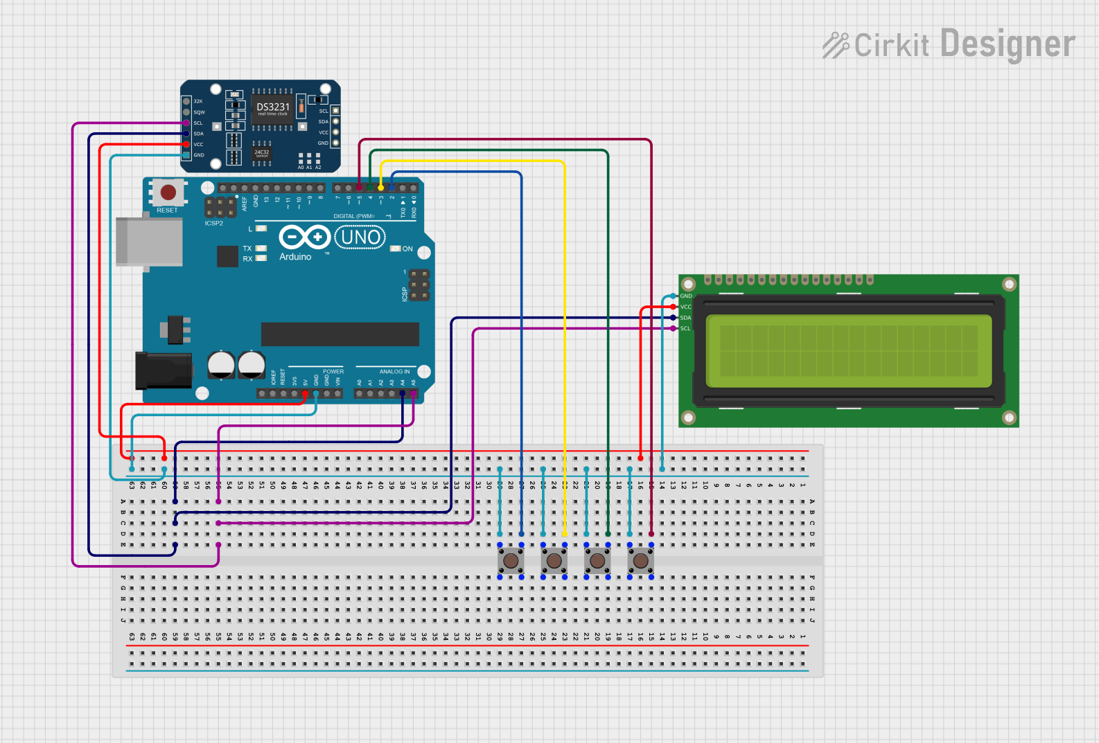
Circuit Documentation
Summary of the Circuit
The circuit in question appears to be a microcontroller-based system utilizing an Arduino UNO as the central processing unit. The circuit includes multiple pushbuttons, a 16x2 I2C LCD display, and a DS3231 Real-Time Clock (RTC) module. The pushbuttons are likely used as input devices, while the LCD and RTC provide output and timekeeping functionality, respectively. The Arduino UNO interfaces with the LCD and RTC via I2C communication, and it monitors the state of the pushbuttons through its digital input pins.
Component List
Pushbutton
- Description: A standard pushbutton used as an input device.
- Pins: Pin 3 (out), Pin 4 (out), Pin 1 (in), Pin 2 (in).
Arduino UNO
- Description: A microcontroller board based on the ATmega328P.
- Pins: UNUSED, IOREF, Reset, 3.3V, 5V, GND, Vin, A0-A5, SCL, SDA, AREF, D0-D13.
16x2 I2C LCD
- Description: A liquid crystal display that communicates over the I2C protocol.
- Pins: GND, VCC, SDA, SCL.
DS3231 RTC
- Description: A highly accurate I2C real-time clock with an integrated temperature-compensated crystal oscillator (TCXO) and crystal.
- Pins: 32K, SQW, SCL, SDA, VCC, GND.
Wiring Details
Pushbuttons
- Pushbutton 1
- Pin 3 (out) connected to Arduino UNO D2.
- Pin 1 (in) connected to common ground.
- Pushbutton 2
- Pin 3 (out) connected to Arduino UNO D3.
- Pin 1 (in) connected to common ground.
- Pushbutton 3
- Pin 3 (out) connected to Arduino UNO D4.
- Pin 1 (in) connected to common ground.
- Pushbutton 4
- Pin 3 (out) connected to Arduino UNO D5.
- Pin 1 (in) connected to common ground.
Arduino UNO
- Digital pins D2, D3, D4, and D5 connected to pushbuttons.
- Analog pins A4 (SDA) and A5 (SCL) used for I2C communication with the LCD and RTC.
- 5V and GND pins provide power to the LCD and RTC modules.
16x2 I2C LCD
- SDA and SCL connected to Arduino UNO A4 and A5, respectively.
- VCC connected to Arduino UNO 5V.
- GND connected to common ground.
DS3231 RTC
- SDA and SCL connected to Arduino UNO A4 and A5, respectively.
- VCC connected to Arduino UNO 5V.
- GND connected to common ground.
Documented Code
Arduino UNO Code (sketch.ino)
void setup() {
  // put your setup code here, to run once:

}

void loop() {
  // put your main code here, to run repeatedly:

}
The provided code is a template with empty setup() and loop() functions, which are the standard structure for Arduino sketches. The setup() function is intended to contain initialization code that runs once at the start, while the loop() function is meant for code that runs continuously.
Additional Notes
There is an additional text file named "documentation.txt" associated with the Arduino UNO microcontroller, but it contains no content. This file may be intended for further elaboration on the code or circuit functionality.