
Arduino Mega 2560 Controlled 12V Blue LED with Relay and LabVIEW Integration
View and Edit Project In Cirkit Designer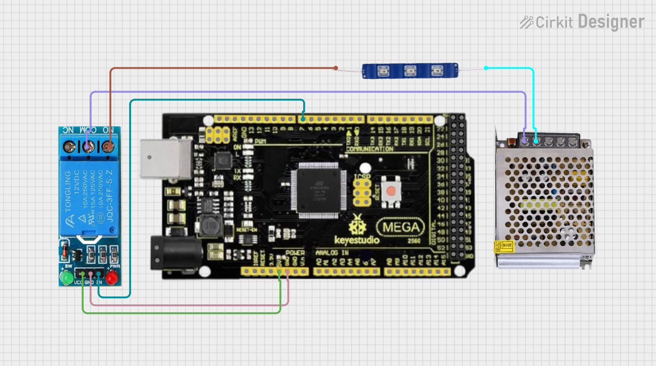
Circuit Documentation
Summary
This circuit is designed to control a 12V Blue LED using a relay, which is managed by an Arduino Mega 2560 R3 microcontroller. The relay is connected to the microcontroller and switches the power to the LED, which is powered by a 12V power supply. The LED can be turned on or off based on signals received from LabVIEW.
Component List
12V Single Channel Relay
- Description: A relay module that can switch a 12V load.
- Pins: NC, COM, NO, IN, GND, VCC
Power Supply 12V 5AMP
- Description: A power supply unit providing 12V DC at up to 5A.
- Pins: 220V Positive Pole (AC), 220V Negative Pole (AC), GND, GND (DC), 12V-24V Output (DC)
12V Blue LED
- Description: A blue LED that operates at 12V.
- Pins: GND, VCC
Mega 2560 R3
- Description: An Arduino microcontroller board based on the ATmega2560.
- Pins: ICSP port GND, ICSP port Reset, ICSP port MOSI, ICSP port SCK, ICSP port +VCC, ICSP port MISO, SCL, SDA, AREF, GND, D13 (PWM), D12 (PWM), D11 (PWM), D10 (PWM), D9 (PWM), D8 (PWM), D7 (PWM), D6 (PWM), D5 (PWM), D4 (PWM), D3 (PWM), D2 (PWM), D1 (TX0), D0 (RX0), D14 (TX3), D15 (RX3), D16 (TX2), D17 (RX2), D18 (TX1), D19 (RX1), D20 (SDA), D21 (SCL), + 5VCC, D22, D23, D24, D25, D26, D27, D28, D29, D30, D31, D32, D33, D34, D35, D36, D37, D38, D39, D40, D41, D42, D43, D44, D45, D46, D47, D48, D49, D50, D51, D52, D53, NC, IOREF, Reset, +3V3, +VCC IN, A0, A1, A2, A3, A4, A5, A6, A7, A8, A9, A10, A11, A12, A13, A14, A15, USB port
Wiring Details
12V Single Channel Relay
- COM connected to 12V-24V Output (DC) of Power Supply 12V 5AMP
- NO connected to VCC of 12V Blue LED
- IN connected to D7 (PWM) of Mega 2560 R3
- GND connected to GND of Mega 2560 R3
- VCC connected to + 5VCC of Mega 2560 R3
Power Supply 12V 5AMP
- 12V-24V Output (DC) connected to COM of 12V Single Channel Relay
- GND (DC) connected to GND of 12V Blue LED
12V Blue LED
- VCC connected to NO of 12V Single Channel Relay
- GND connected to GND (DC) of Power Supply 12V 5AMP
Mega 2560 R3
- D7 (PWM) connected to IN of 12V Single Channel Relay
- GND connected to GND of 12V Single Channel Relay
- + 5VCC connected to VCC of 12V Single Channel Relay
Code Documentation
Arduino Sketch for Mega 2560 R3
/*
 * Arduino Sketch for controlling a 12V Blue LED using a relay
 * via LabVIEW. The relay is connected to pin D7 of the Mega 2560 R3.
 * The relay controls the power to the LED, which is powered by a 12V
 * power supply. The LED will turn on or off based on the signal
 * received from LabVIEW.
 */

// Define pin for relay control
const int relayPin = 7;

void setup() {
  // Initialize the relay pin as an output
  pinMode(relayPin, OUTPUT);
  // Start with the relay off
  digitalWrite(relayPin, LOW);
}

void loop() {
  // Placeholder for LabVIEW communication code
  // For now, we'll just toggle the relay every second
  digitalWrite(relayPin, HIGH); // Turn relay on
  delay(1000); // Wait for 1 second
  digitalWrite(relayPin, LOW); // Turn relay off
  delay(1000); // Wait for 1 second
}
File Name: sketch.ino
This code initializes the relay pin as an output and toggles the relay every second, turning the LED on and off. The placeholder comment indicates where code for LabVIEW communication can be added.