
Arduino-Controlled Air Quality Monitoring System with Relay-Activated Fan and Alert Indicators
View and Edit Project In Cirkit Designer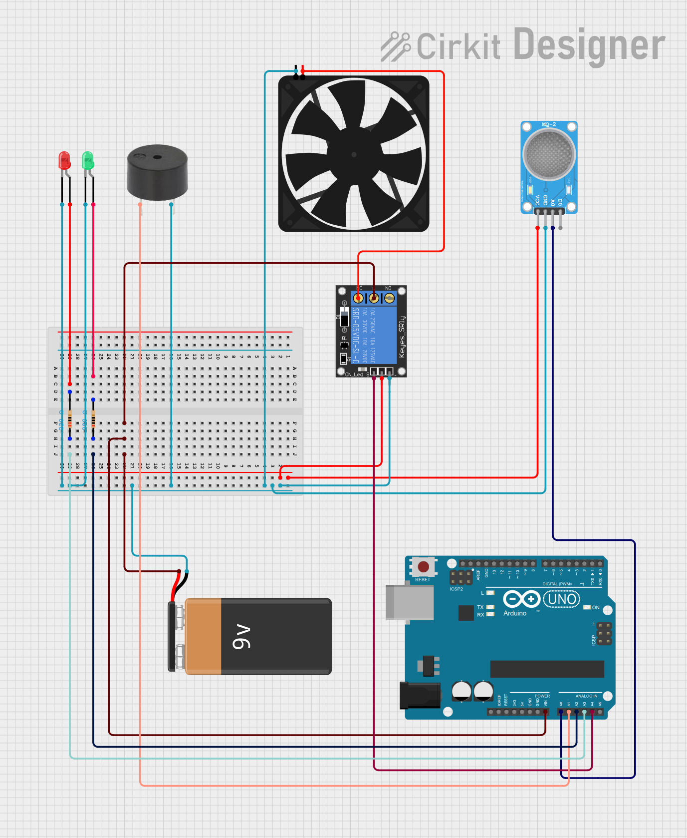
Circuit Documentation
Summary of the Circuit
This circuit is designed to interface various components with an Arduino UNO microcontroller. The circuit includes a 9V battery for power, a two-pin red LED and a two-pin green LED each with a current-limiting resistor, a 1-Channel Relay to control a fan, a buzzer for audio signaling, and an MQ-2 gas sensor for detecting combustible gases. The Arduino UNO is used to control the relay, read sensor data, and manage the LEDs and buzzer based on the sensor inputs.
Component List
LED: Two Pin (red)
- Description: A red light-emitting diode used for indication purposes.
- Pins: cathode, anode
LED: Two Pin (green)
- Description: A green light-emitting diode used for indication purposes.
- Pins: cathode, anode
9V Battery
- Description: Provides power to the circuit.
- Pins: -, +
Arduino UNO
- Description: A microcontroller board based on the ATmega328P used for controlling the circuit.
- Pins: UNUSED, IOREF, Reset, 3.3V, 5V, GND, Vin, A0 to A5, SCL, SDA, AREF, D0 to D13
1-Channel Relay (5V 10A)
- Description: An electromechanical switch used to control high power devices like the fan.
- Pins: NC, signal, C, power, NO, ground
Fan
- Description: An electric fan controlled by the relay.
- Pins: GND, 5V
Buzzer
- Description: An audio signaling device.
- Pins: PIN, GND
MQ-2 SENSOR
- Description: A gas sensor used for detecting a variety of combustible gases.
- Pins: VCC, GND, A0, D0
Resistor (200 Ohms)
- Description: A resistor with a resistance of 200 Ohms, used to limit current through the green LED.
- Pins: pin1, pin2
Resistor (220 Ohms)
- Description: A resistor with a resistance of 220 Ohms, used to limit current through the red LED.
- Pins: pin1, pin2
Wiring Details
LED: Two Pin (red)
- Anode connected to a 220 Ohm resistor.
- Cathode connected to the common ground net.
LED: Two Pin (green)
- Anode connected to a 200 Ohm resistor.
- Cathode connected to the common ground net.
9V Battery
- Positive (+) terminal connected to the common power net (Vin of Arduino and C of Relay).
- Negative (-) terminal connected to the common ground net.
Arduino UNO
- Vin connected to the common power net.
- GND connected to the common ground net.
- A0 connected to the MQ-2 sensor A0 pin.
- A1 connected to the buzzer PIN pin.
- A2 connected to the 200 Ohm resistor pin1.
- A3 connected to the 220 Ohm resistor pin1.
- A4 connected to the relay signal pin.
1-Channel Relay (5V 10A)
- C connected to the common power net.
- Power connected to the MQ-2 sensor VCC pin.
- Ground connected to the common ground net.
- Signal connected to the Arduino A4 pin.
- NC connected to the fan 5V pin.
Fan
- 5V connected to the relay NC pin.
- GND connected to the common ground net.
Buzzer
- PIN connected to the Arduino A1 pin.
- GND connected to the common ground net.
MQ-2 SENSOR
- VCC connected to the relay power pin.
- GND connected to the common ground net.
- A0 connected to the Arduino A0 pin.
Resistor (200 Ohms)
- Pin1 connected to the Arduino A2 pin.
- Pin2 connected to the green LED anode pin.
Resistor (220 Ohms)
- Pin1 connected to the Arduino A3 pin.
- Pin2 connected to the red LED anode pin.
Documented Code
Arduino UNO Code (sketch.ino)
void setup() {
  // put your setup code here, to run once:

}

void loop() {
  // put your main code here, to run repeatedly:

}
Additional Notes (documentation.txt)
No additional code documentation provided.