Arduino UNO-Based Motion-Activated Servo and LED Control System
Circuit Documentation
Summary
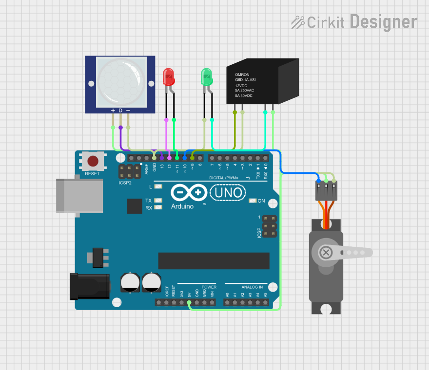
This circuit is designed to detect motion using a PIR motion sensor and respond by activating a servo motor, lighting up LEDs, and controlling a relay. The core of the circuit is an Arduino UNO microcontroller, which processes the input from the PIR sensor and controls the output devices accordingly.
Component List
PIR Motion Sensor (Wokwi Compatible)
- Pins: VCC, OUT, GND
- Description: Detects motion and outputs a signal when motion is detected.
LED: Two Pin (red)
- Pins: Cathode, Anode
- Description: A red LED used to indicate the status of the circuit.
Servo (Wokwi Compatible)
- Pins: GND, V+, PWM
- Description: A servo motor used to perform mechanical movements.
Arduino UNO
- Pins: UNUSED, IOREF, Reset, 3.3V, 5V, GND, Vin, A0, A1, A2, A3, A4, A5, SCL, SDA, AREF, D13, D12, D11, D10, D9, D8, D7, D6, D5, D4, D3, D2, D1, D0
- Description: The main microcontroller that processes inputs and controls outputs.
RELAY-G5D
- Pins: COIL1, COIL2, NO, COM
- Description: A relay used to control high-power devices.
LED: Two Pin (green)
- Pins: Cathode, Anode
- Description: A green LED used to indicate the status of the circuit.
Wiring Details
PIR Motion Sensor (Wokwi Compatible)
- VCC connected to 5V on Arduino UNO
- OUT connected to D13 on Arduino UNO
- GND connected to GND on Arduino UNO
LED: Two Pin (red)
- Cathode connected to D12 on Arduino UNO
- Anode connected to D11 on Arduino UNO
Servo (Wokwi Compatible)
- GND connected to GND on Arduino UNO
- V+ connected to 5V on Arduino UNO
- PWM connected to D10 on Arduino UNO
Arduino UNO
- 5V connected to VCC on PIR Motion Sensor, V+ on Servo, and COM on RELAY-G5D
- GND connected to GND on PIR Motion Sensor, GND on Servo, COIL2 on RELAY-G5D, and Cathode on LED: Two Pin (green)
- D13 connected to OUT on PIR Motion Sensor
- D12 connected to Cathode on LED: Two Pin (red)
- D11 connected to Anode on LED: Two Pin (red)
- D10 connected to PWM on Servo
- D9 connected to COIL1 on RELAY-G5D
RELAY-G5D
- COIL1 connected to D9 on Arduino UNO
- COIL2 connected to GND on Arduino UNO
- NO connected to Anode on LED: Two Pin (green)
- COM connected to 5V on Arduino UNO
LED: Two Pin (green)
- Cathode connected to GND on Arduino UNO
- Anode connected to NO on RELAY-G5D
Documented Code
#include <servo.h>

void setup() {
  DDRB = 0x1E; // Set PB1, PB2, PB3, PB4 as outputs, PB0 and PB5 as inputs
  myServo.attach(PINB2); // attach my servo to the port
}

void loop() {
  if (PINB & (1 << PINB5)) { // Check if PB5 is HIGH
    PORTB |= (1 << PINB4); // Set PB4 HIGH
    delay(300000); // Delay for 5 minutes
    PORTB |= (1 << PINB3); // Set PB3 HIGH
    myServo.write(90); // rotate the servo 90 degree
    delay(3000); // Delay for 3 seconds
    myServo.write(0); // rotate the servo back to original
  }
}
This code initializes the servo motor and sets up the necessary pins on the Arduino UNO. In the main loop, it checks if the PIR sensor has detected motion (PB5 is HIGH). If motion is detected, it activates the relay and the red LED, rotates the servo motor to 90 degrees, waits for 3 seconds, and then returns the servo motor to its original position.