
ESP32 and MPU6050 Battery-Powered Motion Sensor with Bluetooth Connectivity
View and Edit Project In Cirkit Designer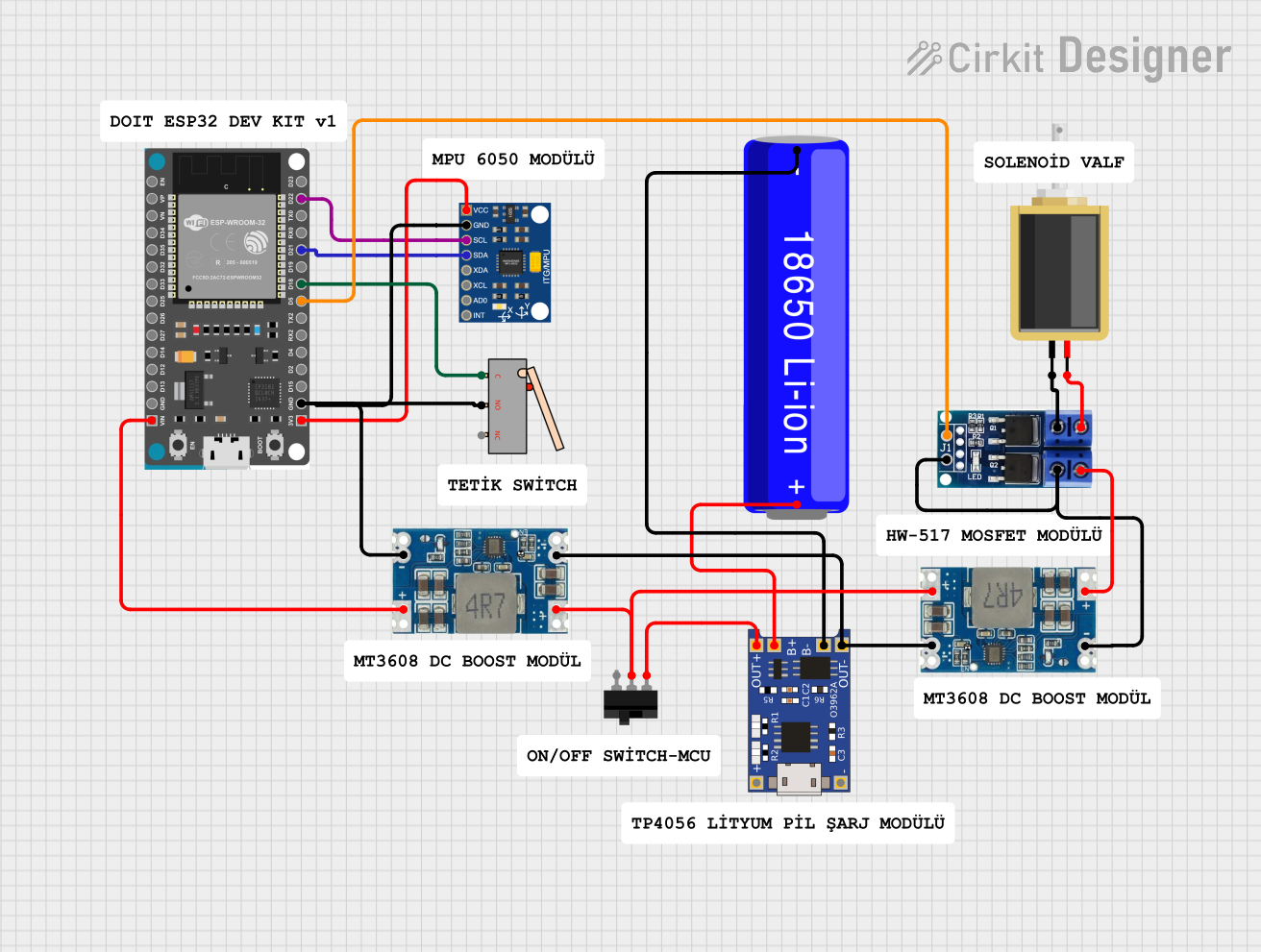
Circuit Documentation
Summary
This circuit is designed to interface an ESP32 microcontroller with an MPU6050 accelerometer and gyroscope sensor, a limit switch, a solenoid, and a motor driver. The circuit is powered by a 18650 Li-ion battery, which is managed by a TP4056 charging module. The power is regulated using Mini 560 step-down converters. The ESP32 communicates with the MPU6050 via I2C and controls the motor driver and solenoid through GPIO pins.
Component List
ESP32 Devkit V1
- Description: A powerful microcontroller with built-in Wi-Fi and Bluetooth capabilities.
- Pins: 3V3, GND, D15, D2, D4, RX2, TX2, D5, D18, D19, D21, RX0, TX0, D22, D23, EN, VP, VN, D34, D35, D32, D33, D25, D26, D27, D14, D12, D13, VIN
InvenSense MPU6050
- Description: A 6-axis motion tracking device that combines a 3-axis gyroscope and a 3-axis accelerometer.
- Pins: VCC, GND, SCL, SDA, XDA, XCL, AD0, INT
18650 Li-ion Battery
- Description: A rechargeable lithium-ion battery.
- Pins: -, +
Mini 560 Step Down 20-7V to 5V
- Description: A step-down voltage regulator that converts 20-7V input to 5V output.
- Pins: IN-, IN+, OUT-, OUT+
TP4056
- Description: A lithium battery charger module with overcharge protection.
- Pins: OUT-, B-, B+, OUT+, IN-, IN+
Limit Switch
- Description: A mechanical switch that can be used to detect the presence or absence of an object.
- Pins: C, NO, NC
Toggle Switch
- Description: A switch that can be toggled between two states.
- Pins: L1, COM, L2
Motor Driver - N-Mos PWM Trigger
- Description: A motor driver that uses PWM signals to control the motor.
- Pins: + PWM, GND, OUT -, OUT +, DC OUT +, DC IN -
Solenoid
- Description: An electromechanical device that converts electrical energy into linear motion.
- Pins: pin1, pin2
Wiring Details
ESP32 Devkit V1
- 3V3: Connected to VCC of MPU6050
- GND: Connected to GND of MPU6050, OUT- of Mini 560 Step Down, and NO of Limit Switch
- D5: Connected to + PWM of Motor Driver
- D18: Connected to C of Limit Switch
- D21: Connected to SDA of MPU6050
- D22: Connected to SCL of MPU6050
- VIN: Connected to OUT+ of Mini 560 Step Down
InvenSense MPU6050
- VCC: Connected to 3V3 of ESP32
- GND: Connected to GND of ESP32
- SCL: Connected to D22 of ESP32
- SDA: Connected to D21 of ESP32
18650 Li-ion Battery
- -: Connected to B- of TP4056
- +: Connected to B+ of TP4056
Mini 560 Step Down 20-7V to 5V (Instance 1)
- IN-: Connected to OUT- of TP4056
- IN+: Connected to COM of Toggle Switch
- OUT-: Connected to GND of ESP32
- OUT+: Connected to VIN of ESP32
Mini 560 Step Down 20-7V to 5V (Instance 2)
- IN-: Connected to OUT- of TP4056
- IN+: Connected to COM of Toggle Switch
- OUT-: Connected to GND and DC IN - of Motor Driver
- OUT+: Connected to DC OUT + of Motor Driver
TP4056
- B-: Connected to - of 18650 Li-ion Battery
- B+: Connected to + of 18650 Li-ion Battery
- OUT-: Connected to IN- of both Mini 560 Step Down converters
- OUT+: Connected to L1 of Toggle Switch
Limit Switch
- C: Connected to D18 of ESP32
- NO: Connected to GND of ESP32
Toggle Switch
- L1: Connected to OUT+ of TP4056
- COM: Connected to IN+ of both Mini 560 Step Down converters
Motor Driver - N-Mos PWM Trigger
- + PWM: Connected to D5 of ESP32
- GND: Connected to OUT- of Mini 560 Step Down
- OUT -: Connected to pin1 of Solenoid
- OUT +: Connected to pin2 of Solenoid
- DC OUT +: Connected to OUT+ of Mini 560 Step Down
- DC IN -: Connected to OUT- of Mini 560 Step Down
Solenoid
- pin1: Connected to OUT - of Motor Driver
- pin2: Connected to OUT + of Motor Driver
Code Documentation
Main Code (sketch.ino)
#include <Arduino.h>
#include <Wire.h>
#include <BluetoothSerial.h>
#include "MPU6050_6Axis_MotionApps20.h"

MPU6050 mpu;
BluetoothSerial SerialBT;

struct Button {
  const uint8_t PIN;
  uint32_t numberKeyPresses;
  bool pressed;
};

volatile bool interruptFlag = true;
unsigned long lastInterruptTime = 0;
const unsigned long debounceTime = 3000;

Button button1 = {18, 0, false};

void IRAM_ATTR isr() {
  unsigned long currentTime = millis();
  if (currentTime - lastInterruptTime < debounceTime) {
    return;
  }
  lastInterruptTime = currentTime;
  button1.numberKeyPresses++;
  button1.pressed = true;
}

#define OUTPUT_READABLE_QUATERNION

bool dmpReady = false;
uint8_t mpuIntStatus;
uint8_t devStatus;
uint16_t packetSize;
uint16_t fifoCount;
uint8_t fifoBuffer[64];

Quaternion q;
VectorInt16 aa;
VectorInt16 aaReal;
VectorInt16 aaWorld;
VectorFloat gravity;
float euler[3];
float ypr[3];

uint8_t teapotPacket[14] = {'$', 0x02, 0, 0, 0, 0, 0, 0, 0, 0, 0x00, 0x00, '\\r', '\\n'};

volatile bool mpuInterrupt = false;
void dmpDataReady() {
  mpuInterrupt = true;
}

void setup() {
  Wire.begin();
  Wire.setClock(400000);

  Serial.begin(115200);
  SerialBT.begin("ESP32_YUSUF");
  SerialBT.print("Bluetooth started");

  pinMode(button1.PIN, INPUT_PULLUP);
  attachInterrupt(button1.PIN, isr, FALLING);

  while (!Serial);

  Serial.println(F("Initializing I2C devices..."));
  mpu.initialize();

  Serial.println(F("Testing device connections..."));
  Serial.println(mpu.testConnection() ? F("MPU6050 connection successful") : F("MPU6050 connection failed"));

  Serial.println(F("Initializing DMP..."));
  devStatus = mpu.dmpInitialize();

  mpu.setXGyroOffset(220);
  mpu.setYGyroOffset(76);
  mpu.setZGyroOffset(-85);
  mpu.setZAccelOffset(1788);

  if (devStatus == 0) {
    mpu.CalibrateAccel(6);
    mpu.CalibrateGyro(6);
    mpu.PrintActiveOffsets();
    Serial.println(F("Enabling DMP..."));
    mpu.setDMPEnabled(true);

    mpuIntStatus = mpu.getIntStatus();
    Serial.println(F("DMP ready! Waiting for first interrupt..."));
    dmpReady = true;
    packetSize = mpu.dmpGetFIFOPacketSize();
  } else {
    Serial.print(F("DMP Initialization failed (code "));
    Serial.print(devStatus);
    Serial.println(F(")"));
  }
}

void loop() {
  if (!dmpReady) return;
  if (mpu.dmpGetCurrentFIFOPacket(fifoBuffer)) {
#ifdef OUTPUT_READABLE_QUATERNION
    mpu.dmpGetQuaternion(&q, fifoBuffer);
    Serial.print(q.w);
    Serial.print(",");
    Serial.print(q.x);
    Serial.print(",");
    Serial.print(q.y);
    Serial.print(",");
    Serial.print