
Circuit Documentation
Summary of the Circuit
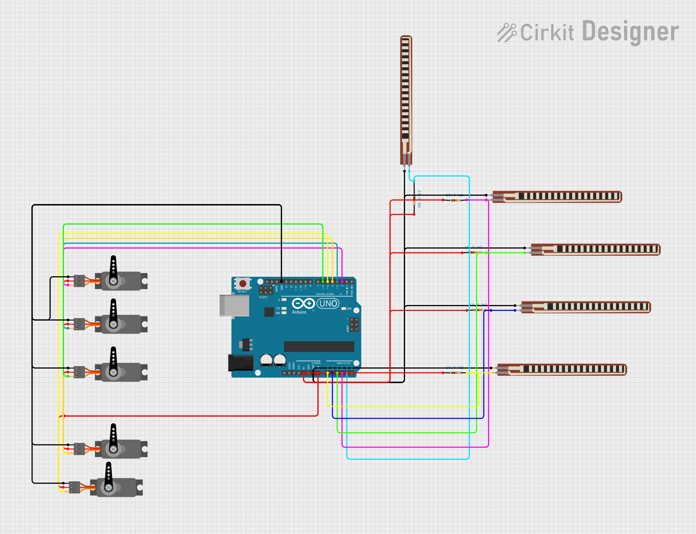
This circuit is designed to control multiple servo motors using flex sensors. The flex sensors are connected to the analog pins of an Arduino UNO microcontroller, which reads the deflection of the sensors and maps them to the rotation angles of the servo motors. The servo motors are connected to the digital pins of the Arduino UNO. The circuit is powered through the Arduino UNO, which distributes power to the servo motors and the flex sensors.
Component List
Microcontroller
- Arduino UNO: A microcontroller board based on the ATmega328P. It has 14 digital input/output pins, 6 analog inputs, a USB connection, a power jack, an ICSP header, and a reset button.
Servo Motors
- Servo: A rotary actuator that allows for precise control of angular position. It has three pins: GND, VCC, and PWM.
Flex Sensors
- 2.2 inch Basic Flex Resistor: A flexible sensor that changes resistance as it is bent. It has two pins: Pin 1 and Pin 2.
Resistors
- Resistor (10k Ohms): A passive two-terminal electrical component that implements electrical resistance as a circuit element.
Wiring Details
Arduino UNO
- GND: Connected to the GND pins of all servo motors and Pin 2 of all flex sensors.
- Vin: Connected to the VCC pins of all servo motors.
- 5V: Connected to one side (pin1) of all 10k Ohm resistors.
- A0 - A4: Connected to the other side (pin1) of the flex sensors through 10k Ohm resistors.
- D2 - D6: Connected to the PWM pins of the servo motors.
Servo Motors
- GND: Connected to the Arduino UNO GND.
- VCC: Connected to the Arduino UNO Vin.
- PWM: Connected to the digital pins D2 - D6 of the Arduino UNO.
Flex Sensors
- Pin 1: Connected to the analog pins A0 - A4 of the Arduino UNO through 10k Ohm resistors.
- Pin 2: Connected to the Arduino UNO GND.
Resistors (10k Ohms)
- pin1: Connected to the 5V pin of the Arduino UNO.
- pin2: Connected to Pin 1 of the flex sensors and analog pins A0 - A4 of the Arduino UNO.
Documented Code
/*
 * Arduino Sketch for Flex Sensors Controlling Servo Motors
 *
 * This code reads the values from multiple flex sensors connected to the analog
 * pins of the Arduino UNO and controls the corresponding servo motors connected
 * to the digital pins. The flex sensor deflection is mapped to the rotation
 * angle of the servo motors.
 */

#include <Servo.h>

// Define servo objects
Servo servo1;
Servo servo2;
Servo servo3;
Servo servo4;
Servo servo5;

// Define analog pins for flex sensors
const int flexSensor1 = A0;
const int flexSensor2 = A1;
const int flexSensor3 = A2;
const int flexSensor4 = A3;
const int flexSensor5 = A4;

// Define digital pins for servos
const int servoPin1 = 2;
const int servoPin2 = 3;
const int servoPin3 = 4;
const int servoPin4 = 5;
const int servoPin5 = 6;

void setup() {
  // Attach servos to their respective pins
  servo1.attach(servoPin1);
  servo2.attach(servoPin2);
  servo3.attach(servoPin3);
  servo4.attach(servoPin4);
  servo5.attach(servoPin5);
}

void loop() {
  // Read flex sensor values
  int flexValue1 = analogRead(flexSensor1);
  int flexValue2 = analogRead(flexSensor2);
  int flexValue3 = analogRead(flexSensor3);
  int flexValue4 = analogRead(flexSensor4);
  int flexValue5 = analogRead(flexSensor5);

  // Map flex sensor values to servo angles (0-180 degrees)
  int angle1 = map(flexValue1, 0, 1023, 0, 180);
  int angle2 = map(flexValue2, 0, 1023, 0, 180);
  int angle3 = map(flexValue3, 0, 1023, 0, 180);
  int angle4 = map(flexValue4, 0, 1023, 0, 180);
  int angle5 = map(flexValue5, 0, 1023, 0, 180);

  // Write angles to servos
  servo1.write(angle1);
  servo2.write(angle2);
  servo3.write(angle3);
  servo4.write(angle4);
  servo5.write(angle5);

  // Small delay to allow servos to reach the position
  delay(15);
}
This code is saved as sketch.ino and is intended to be uploaded to the Arduino UNO microcontroller. It initializes the servo objects, defines the pin connections, and contains the main logic for reading the flex sensor values and controlling the servo motors.