
Circuit Documentation
Summary of the Circuit
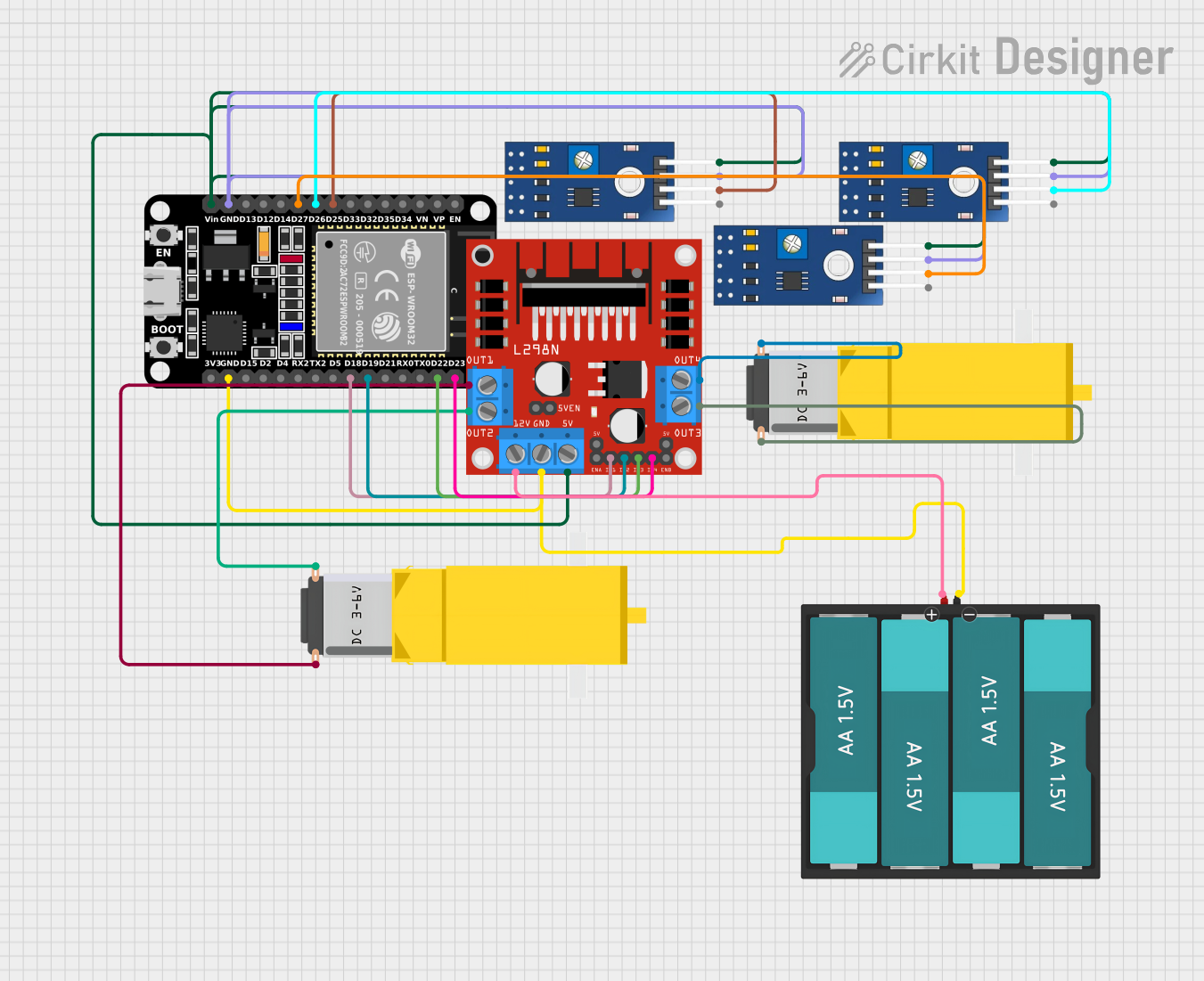
This circuit is designed to control two DC gearmotors using an ESP32 microcontroller and an L298N DC motor driver. The ESP32 reads inputs from three TCRT 5000 IR sensors to make decisions about motor control. The motors are powered by a 6V battery pack consisting of four AA batteries. The L298N motor driver interfaces between the ESP32 and the motors, allowing for the control of motor speed and direction. The IR sensors are used to detect the presence or absence of objects or to measure the reflectivity of surfaces, which can be used in applications such as line following or obstacle avoidance in robotics.
Component List
ESP32 (30 pin)
- Microcontroller with WiFi and Bluetooth capabilities.
- It has a variety of digital I/O pins for interfacing with other components.
Gearmotor DC / Motorreductor
- Two DC gearmotors are used for driving a robotic platform or any mechanical system requiring rotational motion.
L298N DC motor driver
- An H-bridge motor driver capable of driving two DC motors.
- It provides the necessary current amplification from the control signals received from the ESP32.
Battery AAx4 6V
- A battery pack consisting of four AA batteries providing a 6V power supply.
TCRT 5000 IR SENSOR
- Three infrared sensors used for detecting the presence of objects or changes in surface reflectivity.
Wiring Details
ESP32 (30 pin)
D25connected to TCRT 5000 IR SENSOR (DO pin)D26connected to TCRT 5000 IR SENSOR (DO pin)D27connected to TCRT 5000 IR SENSOR (DO pin)D23connected to L298N DC motor driver (IN4 pin)D22connected to L298N DC motor driver (IN3 pin)D19connected to L298N DC motor driver (IN2 pin)D18connected to L298N DC motor driver (IN1 pin)Vinconnected to the 5V power railGNDconnected to the ground rail
Gearmotor DC / Motorreductor
Pin1of the first motor connected to L298N DC motor driver (OUT2 pin)Pin2of the first motor connected to L298N DC motor driver (OUT1 pin)Pin1of the second motor connected to L298N DC motor driver (OUT4 pin)Pin2of the second motor connected to L298N DC motor driver (OUT3 pin)
L298N DC motor driver
IN1,IN2,IN3,IN4connected to ESP32 digital pins for motor controlOUT1,OUT2,OUT3,OUT4connected to the respective pins of the two DC gearmotors12Vconnected to the positive terminal of the Battery AAx4 6V5Vconnected to the 5V power railGNDconnected to the ground rail
Battery AAx4 6V
VCCconnected to L298N DC motor driver (12V pin)GNDconnected to the ground rail
TCRT 5000 IR SENSOR
DOpins connected to ESP32 digital pins (D25, D26, D27)VCCpins connected to the 5V power railGNDpins connected to the ground rail
Documented Code
There is no code provided for the microcontroller. The code would typically include initialization of the GPIO pins, setup of the WiFi or Bluetooth modules if needed, and the main control loop where sensor inputs are read and motor control signals are generated based on the sensor readings.