Arduino Nano Controlled WS2812 RGB LED Strip Light Show
Circuit Documentation
Summary
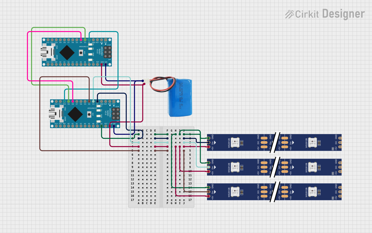
This circuit consists of two Arduino Nano microcontrollers, a 5V battery, and three WS2812 RGB LED strips. The primary Arduino Nano controls the LED strips by sending data signals to each strip's data input pin. The secondary Arduino Nano generates trigger signals that are sent to the primary Arduino Nano to initiate LED blinking sequences. The 5V battery provides power to the entire circuit, ensuring that the microcontrollers and LED strips are adequately powered.
Component List
Arduino Nano
- Microcontroller board based on the ATmega328P
- It has a variety of digital and analog I/O pins
- Capable of serial communication and supports external interrupts
5V Battery
- Provides a 5V power supply to the circuit
- Powers the Arduino Nanos and the WS2812 RGB LED strips
WS2812 RGB LED Strip
- An addressable LED strip with integrated WS2812 RGB LEDs
- Each LED can be individually controlled via a single data line
- Requires a 5V power supply and a ground connection
Wiring Details
Arduino Nano (Primary)
- D2: Connected to the data input (DIN) of the first WS2812 RGB LED strip
- D3: Connected to the data input (DIN) of the second WS2812 RGB LED strip
- D4: Connected to the data input (DIN) of the third WS2812 RGB LED strip
- D8, D9, D10: Connected to the corresponding D4, D3, D2 pins of the secondary Arduino Nano for receiving trigger signals
- VIN: Connected to the positive terminal of the 5V battery
- GND: Connected to the ground of the circuit, including the negative terminal of the 5V battery and the ground pins of the WS2812 RGB LED strips
- 5V: Connected to the 5V pins of the WS2812 RGB LED strips
Arduino Nano (Secondary)
- D2, D3, D4: Connected to the corresponding D10, D9, D8 pins of the primary Arduino Nano to send trigger signals
WS2812 RGB LED Strip (All Strips)
- DIN: Connected to the respective data pins (D2, D3, D4) on the primary Arduino Nano
- 5V: Connected to the 5V power rail of the circuit
- GND: Connected to the ground rail of the circuit
- DO: Data output pin, not used in this circuit
5V Battery
- Positive: Connected to the VIN pin of the primary Arduino Nano and through it to the secondary Arduino Nano
- Negative: Connected to the ground rail of the circuit
Documented Code
Primary Arduino Nano Code
#define LED_PIN1 2       // Data pin for the first LED strip
#define LED_PIN2 3       // Data pin for the second LED strip
#define LED_PIN3 4       // Data pin for the third LED strip

#define TRIGGER_PIN1 10  // Trigger pin for the first strip
#define TRIGGER_PIN2 9   // Trigger pin for the second strip
#define TRIGGER_PIN3 8   // Trigger pin for the third strip

#define NUM_LEDS 10      // Number of LEDs per strip

// Function prototypes
void sendOne(uint8_t pin);
void sendZero(uint8_t pin);
void sendColor(uint8_t pin, uint8_t r, uint8_t g, uint8_t b);
void showStrip(uint8_t pin);
void blinkStrip(uint8_t pin);

void setup() {
  // Initialize LED and trigger pins
  pinMode(LED_PIN1, OUTPUT);
  pinMode(LED_PIN2, OUTPUT);
  pinMode(LED_PIN3, OUTPUT);

  pinMode(TRIGGER_PIN1, INPUT);
  pinMode(TRIGGER_PIN2, INPUT);
  pinMode(TRIGGER_PIN3, INPUT);

  // Ensure LEDs are off initially
  digitalWrite(LED_PIN1, LOW);
  digitalWrite(LED_PIN2, LOW);
  digitalWrite(LED_PIN3, LOW);
}

void loop() {
  // Check for trigger signals and blink the corresponding LED strip
  if (digitalRead(TRIGGER_PIN1) == HIGH) {
    blinkStrip(LED_PIN1);
  }
  if (digitalRead(TRIGGER_PIN2) == HIGH) {
    blinkStrip(LED_PIN2);
  }
  if (digitalRead(TRIGGER_PIN3) == HIGH) {
    blinkStrip(LED_PIN3);
  }
}

// Implementation of functions to control the LED strips
// ...
Secondary Arduino Nano Code
#define TRIGGER_PIN1 2  // Pin D2
#define TRIGGER_PIN2 3  // Pin D3
#define TRIGGER_PIN3 4  // Pin D4

void setup() {
  // Initialize trigger pins as outputs
  pinMode(TRIGGER_PIN1, OUTPUT);
  pinMode(TRIGGER_PIN2, OUTPUT);
  pinMode(TRIGGER_PIN3, OUTPUT);
}

void loop() {
  // Generate trigger signals in sequence
  digitalWrite(TRIGGER_PIN1, HIGH);
  delay(1000);
  digitalWrite(TRIGGER_PIN1, LOW);
  delay(1000);

  digitalWrite(TRIGGER_PIN2, HIGH);
  delay(1000);
  digitalWrite(TRIGGER_PIN2, LOW);
  delay(1000);

  digitalWrite(TRIGGER_PIN3, HIGH);
  delay(1000);
  digitalWrite(TRIGGER_PIN3, LOW);
  delay(1000);
}
This documentation provides an overview of the circuit's components, their wiring, and the embedded code that controls the LED strips. The primary Arduino Nano is responsible for driving the LEDs, while the secondary Arduino Nano generates the trigger signals. The 5V battery supplies power to the entire system.