
Arduino Nano-Controlled Solenoid Actuation System with Load Cell Feedback and SD Logging
View and Edit Project In Cirkit Designer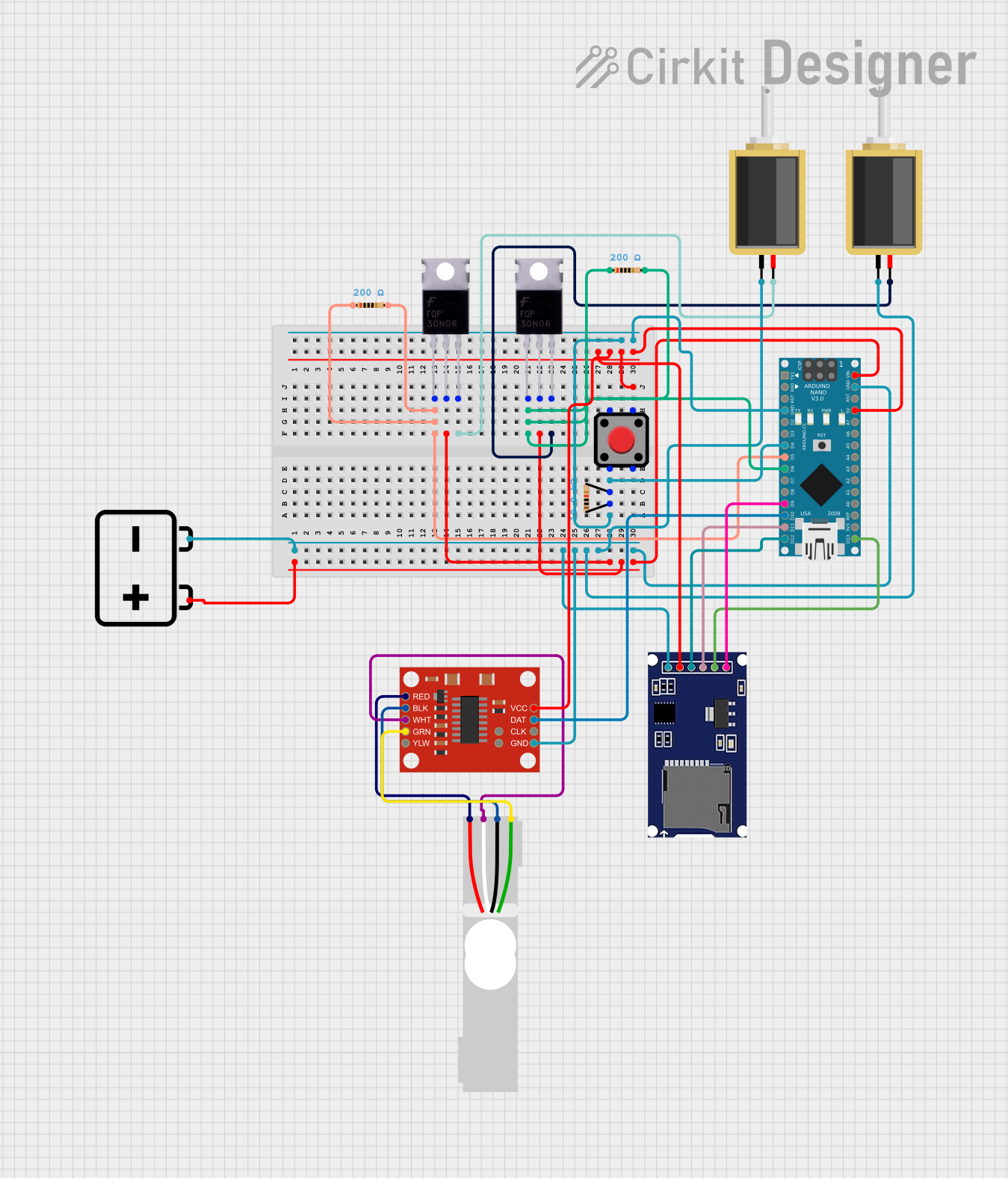
Circuit Documentation
Summary
This circuit is designed to interface with various components including a microcontroller, power supply, sensors, actuators, and communication modules. The core of the circuit is an Arduino Nano, which controls a pair of solenoids through MOSFETs and reads data from a load cell via an HX711 amplifier. The circuit also includes an SD module for data logging. A pushbutton is used for user input, and resistors are employed for current limiting and pull-up configurations.
Component List
12v Battery
- Description: Provides the main power source for the circuit.
SparkFun Load Cell Amplifier - HX711
- Description: Amplifies the signal from the load cell for the microcontroller to read.
Solenoid (x2)
- Description: Actuators controlled by the microcontroller to perform mechanical actions.
Load Cell - Red/white/black/green
- Description: A sensor that measures force or weight.
SDmodule
- Description: A module for logging data onto an SD card.
Arduino Nano
- Description: A microcontroller board based on the ATmega328P, used as the central controller of the circuit.
Resistor (200 Ohms) (x2)
- Description: Used for current limiting or pull-up/pull-down resistors.
Mosfet (x2)
- Description: Transistors used as switches to control high power devices like solenoids.
Resistor (10k Ohms)
- Description: Typically used as a pull-up resistor.
Red Pushbutton
- Description: A user interface component that can trigger events or actions when pressed.
Wiring Details
12v Battery
+connected to the Drain of both MOSFETs and VIN of Arduino Nano.-connected to GND of SDmodule, HX711, both Solenoids, and Arduino Nano.
SparkFun Load Cell Amplifier - HX711
GNDconnected to the 12v Battery-.VCCconnected to 5V of Arduino Nano.DATconnected to D10 of Arduino Nano.CLKnot connected in the provided net list.YLW,GRN,WHT,BLK,RED,B-,B+are load cell connections and not detailed in the net list.
Solenoid
pin1connected to the Source of corresponding MOSFET and GND of the circuit.pin2connected to the Source of corresponding MOSFET.
Load Cell - Red/white/black/green
E+connected toREDof HX711.A-connected toWHTof HX711.E-connected toBLKof HX711.A+connected toGRNof HX711.
SDmodule
CSconnected to D9 of Arduino Nano.SCKconnected to D13/SCK of Arduino Nano.MOSIconnected to D11/MOSI of Arduino Nano.MISOconnected to D12/MISO of Arduino Nano.VCCconnected to 5V of Arduino Nano.GNDconnected to the 12v Battery-.
Arduino Nano
VINconnected to the+of the 12v Battery.GNDconnected to the-of the 12v Battery.5Vconnected to VCC of HX711 and SDmodule.D4connected to one side of the 10k Ohm Resistor and Pin 2 of the Red Pushbutton.D5connected to Gate of one MOSFET through a 200 Ohm Resistor.D6connected to Gate of the other MOSFET through a 200 Ohm Resistor.D9,D10,D11/MOSI,D12/MISO,D13/SCKconnected to corresponding pins on the SDmodule and HX711.
Resistor (200 Ohms) (x2)
- One side connected to D5 or D6 of Arduino Nano.
- Other side connected to Gate of corresponding MOSFET.
Mosfet (x2)
Gateconnected to D5 or D6 of Arduino Nano through a 200 Ohm Resistor.Drainconnected to+of the 12v Battery.Sourceconnected topin2of corresponding Solenoid.
Resistor (10k Ohms)
- One side connected to D4 of Arduino Nano and Pin 2 of the Red Pushbutton.
- Other side connected to GND.
Red Pushbutton
Pin 2connected to one side of the 10k Ohm Resistor and D4 of Arduino Nano.Pin 4connected to 5V of Arduino Nano.Pin 1andPin 3not connected in the provided net list.
Documented Code
Arduino Nano Code (sketch.ino)
void setup() {
  // put your setup code here, to run once:

}

void loop() {
  // put your main code here, to run repeatedly:

}
Additional Notes (documentation.txt)
No additional code documentation was provided.