
Arduino UNO-Based Smart Door Lock System with RFID and Keypad
View and Edit Project In Cirkit Designer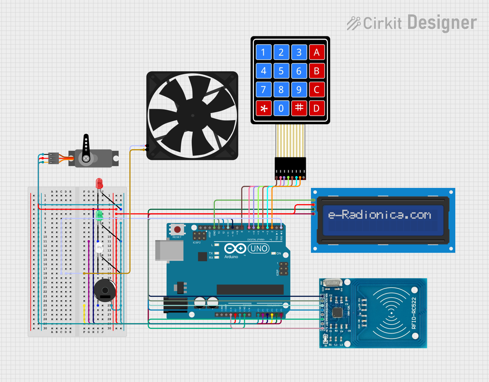
Circuit Documentation
Summary
This circuit is a comprehensive door lock system that integrates various components such as LEDs, a fan, a piezo buzzer, a servo motor, an LCD screen, an RFID reader, and a membrane keypad. The system is controlled by an Arduino UNO microcontroller. The circuit is designed to detect motion, read RFID tags, accept password input via a keypad, and control a servo motor to lock or unlock a door. It also provides visual and auditory feedback using LEDs and a buzzer.
Component List
LED: Two Pin (red)
- Pins: cathode, anode
- Description: Red LED for visual indication.
LED: Two Pin (green)
- Pins: cathode, anode
- Description: Green LED for visual indication.
LED: Two Pin (white)
- Pins: cathode, anode
- Description: White LED for visual indication.
Fan
- Pins: GND, 5V
- Description: Fan for air circulation.
Arduino UNO
- Pins: UNUSED, IOREF, Reset, 3.3V, 5V, GND, Vin, A0, A1, A2, A3, A4, A5, SCL, SDA, AREF, D13, D12, D11, D10, D9, D8, D7, D6, D5, D4, D3, D2, D1, D0
- Description: Microcontroller for controlling the circuit.
Piezo Buzzer
- Pins: pin 1, pin 2
- Description: Buzzer for auditory feedback.
LCD screen 16x2 I2C
- Pins: SCL, SDA, VCC, GND
- Description: LCD screen for displaying messages.
RFID-RC522
- Pins: VCC (3.3V), RST, GND, IRQ, MISO, MOSI, SCK, SDA
- Description: RFID reader for reading RFID tags.
Servo
- Pins: GND, VCC, PWM
- Description: Servo motor for controlling the door lock.
4X4 Membrane Matrix Keypad
- Pins: R1, R2, R3, R4, C1, C2, C3, C4
- Description: Keypad for password input.
Wiring Details
LED: Two Pin (red)
- cathode connected to Arduino UNO A2
- anode connected to GND (shared with other components)
LED: Two Pin (green)
- cathode connected to Arduino UNO A1
- anode connected to GND (shared with other components)
LED: Two Pin (white)
- cathode connected to Fan GND
- anode connected to GND (shared with other components)
Fan
- 5V connected to Arduino UNO D0
- GND connected to GND (shared with other components)
Arduino UNO
- A0 connected to Servo PWM
- A1 connected to LED: Two Pin (green) cathode
- A2 connected to LED: Two Pin (red) cathode
- A3 connected to Piezo Buzzer pin 1
- A4 connected to LCD screen 16x2 I2C SDA
- A5 connected to LCD screen 16x2 I2C SCL
- 3.3V connected to RFID-RC522 VCC (3.3V)
- 5V connected to Servo VCC and LCD screen 16x2 I2C VCC
- GND connected to GND (shared with other components)
- D0 connected to Fan 5V
- D2 connected to 4X4 Membrane Matrix Keypad C3
- D3 connected to 4X4 Membrane Matrix Keypad C2
- D4 connected to 4X4 Membrane Matrix Keypad C1
- D5 connected to 4X4 Membrane Matrix Keypad R4
- D6 connected to 4X4 Membrane Matrix Keypad R3
- D7 connected to 4X4 Membrane Matrix Keypad R2
- D8 connected to 4X4 Membrane Matrix Keypad R1
- D10 connected to RFID-RC522 SDA
- D11 connected to RFID-RC522 MOSI
- D12 connected to RFID-RC522 MISO
- D13 connected to RFID-RC522 SCK
Piezo Buzzer
- pin 1 connected to Arduino UNO A3
- pin 2 connected to GND (shared with other components)
LCD screen 16x2 I2C
- SCL connected to Arduino UNO A5
- SDA connected to Arduino UNO A4
- VCC connected to Arduino UNO 5V
- GND connected to GND (shared with other components)
RFID-RC522
- VCC (3.3V) connected to Arduino UNO 3.3V
- GND connected to GND (shared with other components)
- SCK connected to Arduino UNO D13
- MISO connected to Arduino UNO D12
- MOSI connected to Arduino UNO D11
- SDA connected to Arduino UNO D10
Servo
- GND connected to GND (shared with other components)
- VCC connected to Arduino UNO 5V
- PWM connected to Arduino UNO A0
4X4 Membrane Matrix Keypad
- R1 connected to Arduino UNO D8
- R2 connected to Arduino UNO D7
- R3 connected to Arduino UNO D6
- R4 connected to Arduino UNO D5
- C1 connected to Arduino UNO D4
- C2 connected to Arduino UNO D3
- C3 connected to Arduino UNO D2
Code Documentation
#include <Servo.h>
#include <LiquidCrystal_I2C.h>
#include <Keypad.h>
#include <Password.h>
#include <SPI.h>
#include <MFRC522.h>

#define buzzer A3
#define ledr A2
#define ledg A1
#define SS_PIN 10
#define RST_PIN 9
#define PIR_PIN 1
#define HOME_LED 0

String UID2 = "B3 06 14 32";
String UID1 = "43 D1 16 BE";
String UID0 = "76 C4 52 00";

Servo servo;

LiquidCrystal_I2C lcd(0x27, 16, 2);
MFRC522 rfid(SS_PIN, RST_PIN);

String newPasswordString;
char newPassword[6];

byte a = 5;
byte lock = 0;
bool value = true;
int state;

Password password = Password("0657");
byte maxPasswordLength = 6;
byte currentPasswordLength = 0;

const byte ROWS = 4;
const byte COLS = 4;

char keys[ROWS][COLS] = {
  {'1', '2', '3'},
  {'4', '5', '6'},
  {'7', '8', '9'},
  {'*', '0', '#'},
};

byte rowPins[ROWS] = {8, 7, 6, 5};
byte colPins[COLS] = {4, 3, 2};
Keypad keypad = Keypad(makeKeymap(keys), rowPins, colPins, ROWS, COLS);

void setup() {
  Serial.begin(9600);
  pinMode(ledr, OUTPUT);
  pinMode(ledg, OUTPUT);
  pinMode(buzzer, OUTPUT);
  pinMode(PIR_PIN, INPUT);
  pinMode(HOME_LED, OUTPUT);
  SPI.begin();
  rfid.PCD_Init();
  servo.attach(A0);
  digitalWrite(9, HIGH);
  servo.write(0);
  lcd.init();
  lcd.backlight();
  lcd.setCursor(3, 0);
  lcd.print("WELCOME TO");
  lcd.setCursor(0, 1);
  lcd.print("DOOR LOCK SYSTEM");
  delay(3000);
  lcd.clear();
}

void loop() {
  if (digitalRead(PIR_PIN) == HIGH) {
    digitalWrite(HOME_LED,