
Arduino-Controlled Solar Tracking System with Stepper Motor and LDR Sensors
View and Edit Project In Cirkit Designer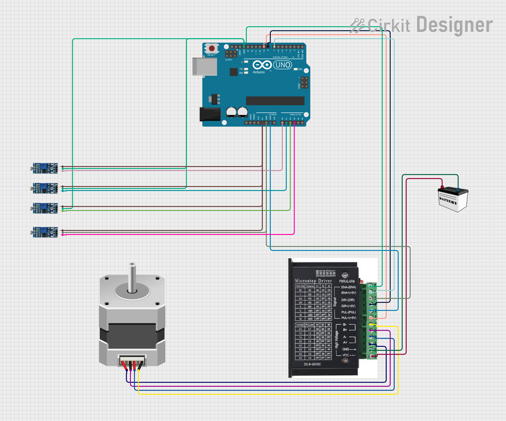
Circuit Documentation
Summary
This circuit is designed to control a bipolar stepper motor using an Arduino UNO microcontroller and a stepper driver. The circuit also includes multiple LDR (Light Dependent Resistor) modules to sense light intensity, which may be used to guide the stepper motor's movements. A 12V battery powers the stepper driver, while the Arduino UNO is powered by its 5V pin. The Arduino UNO reads the analog values from the LDR modules and controls the stepper motor's direction and steps through the stepper driver.
Component List
Stepper Motor (Bipolar)
- Description: A bipolar stepper motor capable of precise movements.
- Purpose: To perform controlled rotational movements based on signals from the Arduino UNO.
12V Battery (Small Size)
- Description: A 12V power source used to power the stepper driver.
- Purpose: To provide the necessary voltage and current to drive the stepper motor.
Arduino UNO
- Description: A microcontroller board based on the ATmega328P.
- Purpose: To process sensor inputs and control the stepper driver, thereby managing the stepper motor's movements.
Stepper Driver
- Description: A driver module for controlling bipolar stepper motors.
- Purpose: To amplify the control signals from the Arduino UNO and drive the stepper motor.
LDR Module 3 pin
- Description: A module with a light-dependent resistor that outputs a digital signal.
- Purpose: To sense the intensity of light and provide input to the Arduino UNO for decision-making.
Wiring Details
Stepper Motor (Bipolar)
- Connections:
- Motor Coil 1: Connected to the stepper driver's A+ and A-.
- Motor Coil 2: Connected to the stepper driver's B+ and B-.
12V Battery (Small Size)
- Connections:
- VCC: Connected to the stepper driver's VCC.
- GND: Connected to the stepper driver's GND.
Arduino UNO
- Connections:
- 5V: Powers the LDR modules.
- GND: Common ground for the LDR modules and stepper driver.
- Digital Pins (D7, D8, D9): Control signals to the stepper driver (ENA-, DIR+, PUL+).
- Analog Pins (A0, A1, A2, A3): Receive analog inputs from the LDR modules.
Stepper Driver
- Connections:
- ENA, ENA-: Enable signal from the Arduino UNO (D7).
- DIR+, DIR-: Direction signal from the Arduino UNO (D8).
- PUL+, PUL-: Pulse signal from the Arduino UNO (D9).
- A+, A-, B+, B-: Connections to the stepper motor.
- VCC, GND: Power input from the 12V battery.
LDR Module 3 pin
- Connections:
- VCC: Powered by the Arduino UNO's 5V pin.
- GND: Common ground with the Arduino UNO.
- DO: Digital output connected to the Arduino UNO's analog pins (A0, A1, A2, A3).
Documented Code
// Define pin connections to TB6600 driver
const int stepPin = 9; // Pulse pin
const int dirPin = 8;  // Direction pin
const int enablePin = 7; // Enable pin

// Define pins for LDR sensors
const int LDRTopLeft = A0;     // LDR 1 (Top-Left)
const int LDRTopRight = A1;    // LDR 2 (Top-Right)
const int LDRBottomLeft = A2;  // LDR 3 (Bottom-Left)
const int LDRBottomRight = A3; // LDR 4 (Bottom-Right)

// Optional: Define pins for limit switches
const int limitSwitch1 = 2; // Limit switch for 0 degrees
const int limitSwitch2 = 3; // Limit switch for 180 degrees

// Threshold to determine when the light is balanced
const int threshold = 50; // Adjust this value based on sensor sensitivity

// Steps per revolution (adjust based on your stepper motor)
const int stepsPerRevolution = 200; // Nema 17 (200 steps per 360°)
const int microsteps = 16;          // Microstepping setting on TB6600
const int stepsPerDegree = (stepsPerRevolution * microsteps) / 360;

void setup() {
  // Set pins as outputs
  pinMode(stepPin, OUTPUT);
  pinMode(dirPin, OUTPUT);
  pinMode(enablePin, OUTPUT);

  // Optional: Set up limit switches
  pinMode(limitSwitch1, INPUT_PULLUP);
  pinMode(limitSwitch2, INPUT_PULLUP);

  // Enable the motor
  digitalWrite(enablePin, LOW); // LOW = motor enabled, HIGH = motor disabled

  Serial.begin(9600); // Debugging output
}

void loop() {
  // Read values from the LDR sensors
  int topLeftValue = analogRead(LDRTopLeft);
  int topRightValue = analogRead(LDRTopRight);
  int bottomLeftValue = analogRead(LDRBottomLeft);
  int bottomRightValue = analogRead(LDRBottomRight);

  // Calculate the averages for top and bottom, left and right
  int topAverage = (topLeftValue + topRightValue) / 2;
  int bottomAverage = (bottomLeftValue + bottomRightValue) / 2;
  int leftAverage = (topLeftValue + bottomLeftValue) / 2;
  int rightAverage = (topRightValue + bottomRightValue) / 2;

  // Check if the panel needs to move horizontally (left or right)
  if (abs(leftAverage - rightAverage) > threshold) {
    if (leftAverage > rightAverage) {
      // Rotate left
      rotatePanel('L');
    } else {
      // Rotate right
      rotatePanel('R');
    }
  }

  // Check if the panel needs to move vertically (up or down)
  if (abs(topAverage - bottomAverage) > threshold) {
    if (topAverage > bottomAverage) {
      // Rotate up
      rotatePanel('U');
    } else {
      // Rotate down
      rotatePanel('D');
    }
  }

  delay(1000); // Delay to avoid rapid motor movements
}

// Function to rotate the panel
void rotatePanel(char direction) {
  // Set direction based on input
  if (direction == 'L') {
    Serial.println("Rotating Left");
    digitalWrite(dirPin, LOW);  // Clockwise
  } else if (direction == 'R') {
    Serial.println("Rotating Right");
    digitalWrite(dirPin, HIGH); // Counterclockwise
  } else if (direction == 'U') {
    Serial.println("Rotating Up");
    digitalWrite(dirPin, LOW);  // Clockwise (depends on motor axis setup)
  } else if (direction == 'D') {
    Serial.println("Rotating Down");
    digitalWrite(dirPin, HIGH); // Counterclockwise (depends on motor axis setup)
  }

  // Rotate motor for a small step
  for (int i = 0; i < 10 * stepsPerDegree; i++) {
    digitalWrite(stepPin, HIGH);
    delayMicroseconds(500);
    digitalWrite(stepPin, LOW);
    delayMicroseconds(500);
  }

  // Optional: Use limit switches to stop at end points
  if (digitalRead(limitSwitch1) == LOW && direction == 'L') {
    // If the limit switch for 0 degrees is pressed, stop movement
    return;
  }
  if (digitalRead(limitSwitch2) == LOW && direction == 'R') {
    // If the limit switch for 180 degrees is pressed, stop movement
    return;
  }
}
This code is designed to be uploaded to an Arduino UNO microcontroller. It includes the setup of input and output pins, reading from LDR sensors, and controlling a stepper motor through a driver based on the sensor readings. The code also contains a function to rotate the panel in a specified direction and includes optional code for limit switches to prevent over-rotation.