
Arduino-Controlled IR Sensor Fire Detection System with Buzzer Alert and Water Pump Activation
View and Edit Project In Cirkit Designer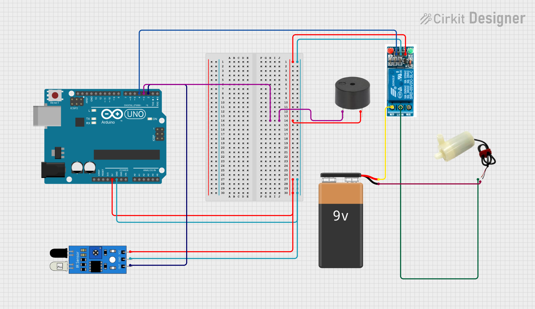
Circuit Documentation
Summary of the Circuit
This circuit is designed to detect a specific condition using an IR sensor and respond by activating a buzzer and a water pump through a 5V relay. The system is controlled by an Arduino UNO microcontroller, which reads the sensor data and controls the relay and buzzer accordingly. The circuit is powered by a 9V battery, which is stepped down to 5V by the Arduino to power the components.
Component List
9V Battery
- Description: Provides the power source for the circuit.
- Pins: Negative (-), Positive (+)
Buzzer
- Description: Emits an audible alert when activated.
- Pins: PIN, GND
5V Mini Water Pump
- Description: Pumps water when activated.
- Pins: Positive Pin, Negative Pin
5V Relay
- Description: Acts as an electrically operated switch to control the water pump.
- Pins: Normally Open (NO), Common Terminal (COM), Normally Closed (NC), Input (In), Ground (GND), Voltage Supply (VCC)
Arduino UNO
- Description: The main microcontroller unit that controls the circuit logic.
- Pins: Various digital and analog pins, power supply pins (3.3V, 5V, GND, Vin), and communication pins (SCL, SDA, AREF).
IR Sensor
- Description: Detects the specific condition (e.g., presence of an object or a change in the environment).
- Pins: Output (out), Ground (gnd), Voltage Supply (vcc)
Wiring Details
9V Battery
- Negative (-): Connected to the negative pin of the 5V mini water pump.
- Positive (+): Connected to the Normally Open pin of the 5V relay.
Buzzer
- PIN: Connected to digital pin D3 of the Arduino UNO.
- GND: Connected to the GND pin of the 5V relay, IR sensor, and Arduino UNO.
5V Mini Water Pump
- Positive Pin: Connected to the Common Terminal of the 5V relay.
- Negative Pin: Connected to the negative (-) terminal of the 9V Battery.
5V Relay
- VCC: Connected to the 5V pin of the Arduino UNO, VCC pin of the IR sensor, and GND pin of the buzzer.
- GND: Connected to the GND pin of the IR sensor and Arduino UNO.
- Normally Open (NO): Connected to the positive (+) terminal of the 9V Battery.
- Common Terminal (COM): Connected to the positive pin of the 5V mini water pump.
- In: Connected to digital pin D4 of the Arduino UNO.
Arduino UNO
- 5V: Provides power to the VCC pin of the 5V relay and IR sensor.
- GND: Common ground for the buzzer, 5V relay, and IR sensor.
- D3: Controls the buzzer.
- D4: Controls the input to the 5V relay.
- D2: Reads the output from the IR sensor.
IR Sensor
- out: Connected to digital pin D2 of the Arduino UNO.
- gnd: Connected to the GND pin of the Arduino UNO and 5V relay.
- vcc: Connected to the 5V pin of the Arduino UNO.
Documented Code
#define SENSOR_PIN 2
#define BUZZER_PIN 3
#define RELAY_PIN 4

void setup()
{
  pinMode(RELAY_PIN, OUTPUT);
  pinMode(SENSOR_PIN, INPUT);
  pinMode(BUZZER_PIN, OUTPUT);

  Serial.begin(9600);  // Start serial communication for plotting

  digitalWrite(RELAY_PIN, HIGH);  // Ensure sprinkler is OFF initially (HIGH if LOW-level triggered)
  digitalWrite(BUZZER_PIN, LOW);  // Ensure buzzer is OFF initially
}

void loop()
{
  int sensorValue = digitalRead(SENSOR_PIN);  // Read fire sensor value
  int buzzerStatus = 0;  // Initialize buzzer status (0 = OFF)

  // Sending a series of values (1 through 10) to Serial Monitor for demonstration
  for (int i = 1; i <= 10; i++) {
    Serial.println(i);  // Simulate sensor value changes or other data for plotting
  }

  // Send sensor value for plotting as the first value
  Serial.print(sensorValue);  // Print sensor value for plotting
  Serial.print(" ");  // Separate sensor value and buzzer value with a space

  // Check fire detection and control buzzer/relay
  if (sensorValue == HIGH)  // Fire detected
  {
    digitalWrite(BUZZER_PIN, HIGH);  // Turn on buzzer immediately
    buzzerStatus = 1;  // Buzzer on
    delay(2000);  // 2-second delay before activating sprinkler
    digitalWrite(RELAY_PIN, LOW);  // Turn On sprinkler (relay is LOW-level triggered)
  }
  else  // No fire detected
  {
    digitalWrite(BUZZER_PIN, LOW);  // Turn off buzzer
    buzzerStatus = 0;  // Buzzer off
    digitalWrite(RELAY_PIN, HIGH);  // Turn Off sprinkler (relay is LOW-level triggered)
  }

  // Send buzzer status for plotting as the second value
  Serial.println(buzzerStatus);  // Print buzzer status (0 or 1)

  delay(5);  // Small delay for better plotting resolution
}
This code is designed to be uploaded to the Arduino UNO microcontroller. It initializes the pins for the sensor, buzzer, and relay, and contains a main loop that reads the sensor value, activates the buzzer, and controls the relay based on the sensor input. It also sends data to the serial monitor for plotting or debugging purposes.