Cirkit Designer
Your all-in-one circuit design IDE
Home /
Project Documentation
Arduino UNO Fish Feeder with RTC and Servo Motor
Circuit Documentation
Summary
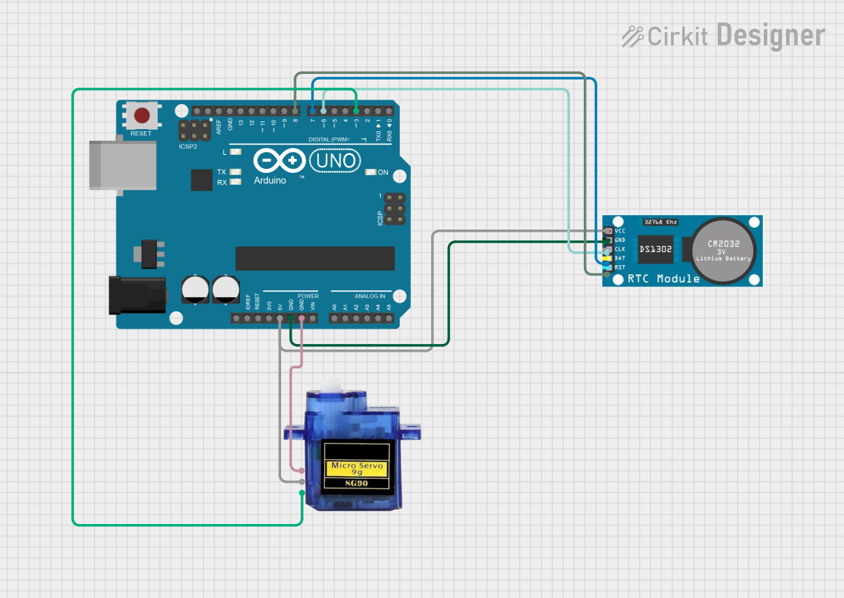
This circuit is designed to control a micro servo motor based on the time provided by an RTC (Real-Time Clock) module. The system uses an Arduino UNO as the main microcontroller. The RTC module keeps track of the current time, and the Arduino UNO reads this time to determine when to activate the servo motor. The servo motor is used to perform a specific action, such as feeding fish at predetermined times.
Component List
Arduino UNO
- Description: A microcontroller board based on the ATmega328P.
- Pins: UNUSED, IOREF, Reset, 3.3V, 5V, GND, Vin, A0, A1, A2, A3, A4, A5, SCL, SDA, AREF, D13, D12, D11, D10, D9, D8, D7, D6, D5, D4, D3, D2, D1, D0
RTC (Real-Time Clock)
- Description: A module used to keep track of the current time.
- Pins: VCC, GND, CLK, DAT, RST
Micro Servo 9G
- Description: A small servo motor used for precise control of angular position.
- Pins: GND, +5V, PWM
Wiring Details
Arduino UNO
- 5V: Connected to VCC of RTC and +5V of Micro Servo 9G
- GND: Connected to GND of RTC and GND of Micro Servo 9G
- D8: Connected to RST of RTC
- D7: Connected to DAT of RTC
- D6: Connected to CLK of RTC
- D3: Connected to PWM of Micro Servo 9G
RTC (Real-Time Clock)
- VCC: Connected to 5V of Arduino UNO
- GND: Connected to GND of Arduino UNO
- CLK: Connected to D6 of Arduino UNO
- DAT: Connected to D7 of Arduino UNO
- RST: Connected to D8 of Arduino UNO
Micro Servo 9G
- GND: Connected to GND of Arduino UNO
- +5V: Connected to 5V of Arduino UNO
- PWM: Connected to D3 of Arduino UNO
Code Documentation
Arduino Code
#include <Wire.h>
#include <RTClib.h>
#include <Servo.h>

RTC_DS1307 rtc;
Servo myServo;

void setup() {
  Serial.begin(9600);
  Wire.begin();
  rtc.begin();
  myServo.attach(9); // Attach servo to pin D9

  if (!rtc.isrunning()) {
    Serial.println("RTC is NOT running!");
    // Set the RTC to the current date and time
    rtc.adjust(DateTime(F(__DATE__), F(__TIME__)));
  }
}

void loop() {
  DateTime now = rtc.now();

  // Feed the fish at 7:00 AM, 12:00 PM, and 6:00 PM
  if ((now.hour() == 7 && now.minute() == 0) ||
      (now.hour() == 12 && now.minute() == 0) ||
      (now.hour() == 18 && now.minute() == 0)) {
    feedFish();
  }

  delay(60000); // Check every minute
}

void feedFish() {
  myServo.write(90); // Rotate servo to 90 degrees
  delay(10000);      // Wait for 10 seconds
  myServo.write(0);  // Rotate servo back to 0 degrees
}
Code Explanation
- Libraries: The code includes three libraries:
Wire.hfor I2C communication,RTClib.hfor RTC functionality, andServo.hfor controlling the servo motor. - RTC Initialization: The RTC is initialized in the
setup()function. If the RTC is not running, it is set to the current date and time. - Servo Initialization: The servo motor is attached to pin D9.
- Main Loop: The
loop()function checks the current time every minute. If the time matches 7:00 AM, 12:00 PM, or 6:00 PM, thefeedFish()function is called. - Feeding Function: The
feedFish()function rotates the servo to 90 degrees, waits for 10 seconds, and then rotates it back to 0 degrees.
This documentation provides a comprehensive overview of the circuit, including the components used, their wiring, and the code that controls the system.