
ESP-8266 Smart Irrigation System with Ultrasonic and Soil Moisture Sensors
View and Edit Project In Cirkit Designer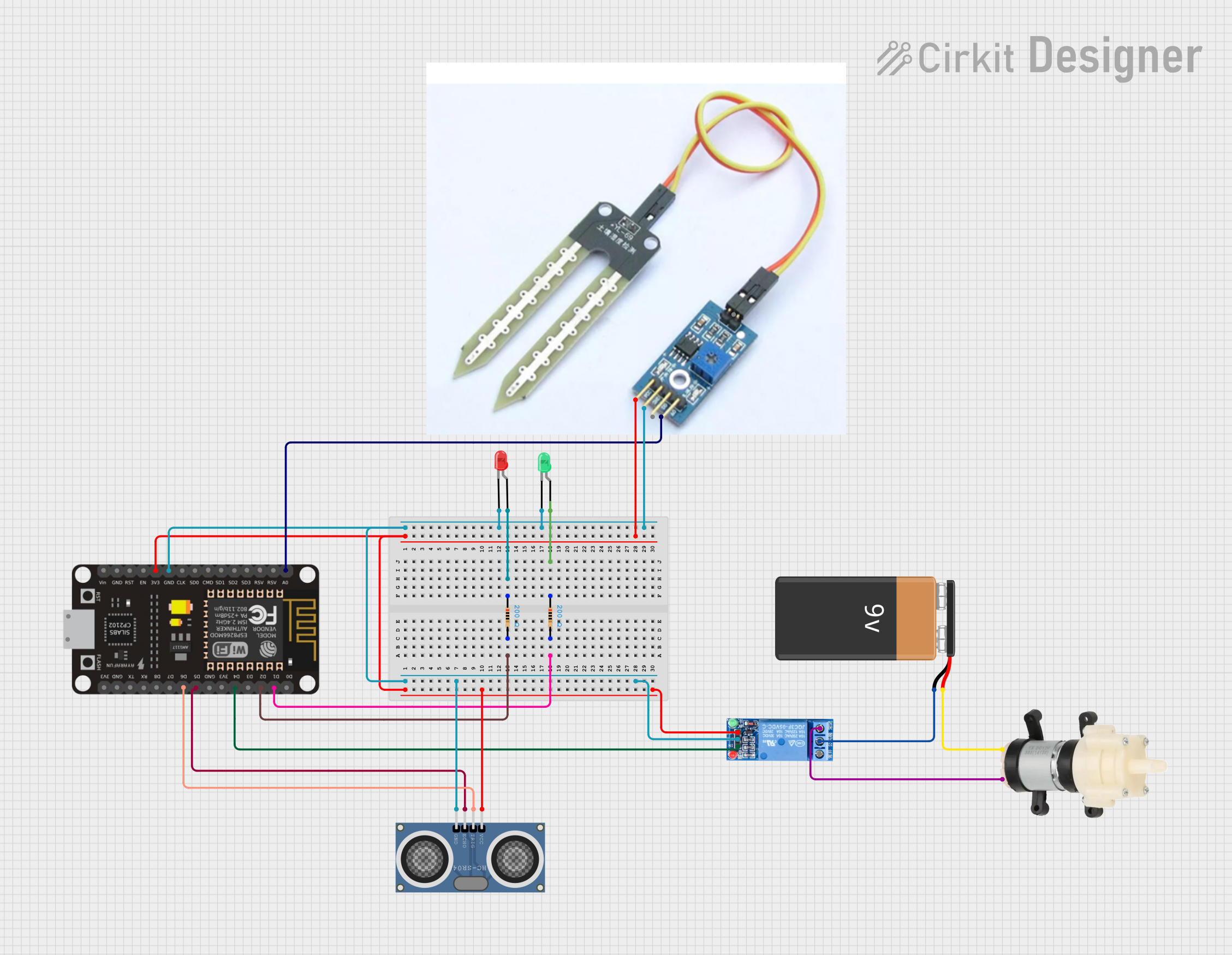
Circuit Documentation
Summary
This circuit is designed to monitor soil moisture levels and control a water pump based on the moisture readings. It also includes an ultrasonic distance sensor to measure distance and two LEDs to indicate different states. The circuit is controlled by an ESP-8266 microcontroller, which communicates with a Blynk application for remote monitoring and control.
Component List
ESP-8266 Controller
- Description: A Wi-Fi enabled microcontroller used to control the circuit and communicate with the Blynk application.
- Pins: A0, RSV, SD3, SD5, SD1, CMD, D0, D1, D2, D3, D4, 3V3, GND, D5, D6, SD0, CLK, RST, EN, D7, D8, RX, TX, Vin, 5V
HC-SR04 Ultrasonic Distance Sensor (Wokwi Compatible)
- Description: A sensor used to measure distance by emitting ultrasonic waves and measuring the time it takes for the echo to return.
- Pins: VCC, TRIG, ECHO, GND
Soil Sensor
- Description: A sensor used to measure the moisture level in the soil.
- Pins: VCC, GND, D0, A0
LED: Two Pin (red)
- Description: A red LED used to indicate a specific state in the circuit.
- Pins: Cathode, Anode
LED: Two Pin (green)
- Description: A green LED used to indicate a specific state in the circuit.
- Pins: Cathode, Anode
9V Battery
- Description: A power source for the circuit.
- Pins: -, +
Mini Diaphragm Water Pump
- Description: A water pump used to water the soil based on the moisture readings.
- Pins: Positive (+), Negative (-)
1 Channel Relay 5V
- Description: A relay used to control the water pump.
- Pins: VCC, GND, IN, NC, COM, NO
Resistor (200 Ohms)
- Description: A resistor used to limit current to the LEDs.
- Pins: Pin1, Pin2
Wiring Details
ESP-8266 Controller
- D2: Connected to Pin2 of a 200 Ohm Resistor
- D1: Connected to Pin2 of another 200 Ohm Resistor
- 3V3: Connected to VCC of HC-SR04 Ultrasonic Distance Sensor, Soil Sensor, and 1 Channel Relay 5V
- GND: Connected to GND of HC-SR04 Ultrasonic Distance Sensor, Cathode of Red LED, Cathode of Green LED, GND of 1 Channel Relay 5V, and GND of Soil Sensor
- A0: Connected to A0 of Soil Sensor
- D4: Connected to IN of 1 Channel Relay 5V
- D5: Connected to ECHO of HC-SR04 Ultrasonic Distance Sensor
- D6: Connected to TRIG of HC-SR04 Ultrasonic Distance Sensor
HC-SR04 Ultrasonic Distance Sensor (Wokwi Compatible)
- VCC: Connected to 3V3 of ESP-8266 Controller
- GND: Connected to GND of ESP-8266 Controller
- ECHO: Connected to D5 of ESP-8266 Controller
- TRIG: Connected to D6 of ESP-8266 Controller
Soil Sensor
- VCC: Connected to 3V3 of ESP-8266 Controller
- GND: Connected to GND of ESP-8266 Controller
- A0: Connected to A0 of ESP-8266 Controller
LED: Two Pin (red)
- Anode: Connected to Pin1 of a 200 Ohm Resistor
- Cathode: Connected to GND of ESP-8266 Controller
LED: Two Pin (green)
- Anode: Connected to Pin1 of another 200 Ohm Resistor
- Cathode: Connected to GND of ESP-8266 Controller
9V Battery
- -: Connected to COM of 1 Channel Relay 5V
- +: Connected to Positive (+) of Mini Diaphragm Water Pump
Mini Diaphragm Water Pump
- Positive (+): Connected to + of 9V Battery
- Negative (-): Connected to NO of 1 Channel Relay 5V
1 Channel Relay 5V
- VCC: Connected to 3V3 of ESP-8266 Controller
- GND: Connected to GND of ESP-8266 Controller
- IN: Connected to D4 of ESP-8266 Controller
- COM: Connected to - of 9V Battery
- NO: Connected to Negative (-) of Mini Diaphragm Water Pump
Resistor (200 Ohms)
- Pin1: Connected to Anode of Red LED
- Pin2: Connected to D2 of ESP-8266 Controller
Resistor (200 Ohms)
- Pin1: Connected to Anode of Green LED
- Pin2: Connected to D1 of ESP-8266 Controller
Documented Code
#define ECO 14
#define GAT 12
#define LED1 4
#define LED2 5
#define RELÉ 2

char auth[] = BLYNK_AUTH_TOKEN;
char ssid[] = "A";
char pass[] = "rapaz2009";
BlynkTimer timer;
long duração, distancia;
int value;
int porcento;

void sendSensor()
{
  int value = analogRead(A0);
  porcento = map(value,0,1023,483,0);
  Blynk.virtualWrite(V0, porcento);
}

void setup()
{
  Serial.begin(115200);
  pinMode(GAT, OUTPUT);
  pinMode(ECO, INPUT);
  pinMode(RELÉ, OUTPUT); // RELÉ
  pinMode(LED1, OUTPUT); // LED 1
  pinMode(LED2, OUTPUT); // LED 2
  Blynk.begin(auth, ssid, pass);
  timer.setInterval(100L, sendSensor);
}

void loop()
{
  digitalWrite(GAT, LOW);
  delayMicroseconds(2);
  digitalWrite(GAT, HIGH);
  delayMicroseconds(10);
  digitalWrite(GAT, LOW);

  duração = pulseIn(ECO, HIGH);
  distancia = duração / 58.2;
  String disp = String(distancia);

  Blynk.virtualWrite(V1, distancia);

  Serial.print("Distancia: ");
  Serial.print(disp);
  Serial.println(" cm");
  delay(1000);

  if (distancia < 10){
     digitalWrite(LED2, HIGH);
     digitalWrite(LED1, LOW);

  if (porcento < 10){
     digitalWrite(LED2, LOW);
     digitalWrite(LED1, HIGH);
     digitalWrite(RELÉ, HIGH);
    }
    else {
     digitalWrite(LED2, HIGH);
     digitalWrite(LED1, LOW);
     digitalWrite(RELÉ, LOW);
    }
  }
  else {
     digitalWrite(LED2, LOW);
     digitalWrite(LED1, HIGH);
     delay(800);
     digitalWrite(LED1, LOW);
     delay(100);
     digitalWrite(RELÉ, LOW);
    }
  Blynk.run();
  timer.run();
}
This code is designed to read the soil moisture level and distance, control the LEDs and relay based on the readings, and communicate with the Blynk application for remote monitoring and control.