
Arduino UNO-Based Fire and Smoke Detection System with GSM Alert and LCD Display
View and Edit Project In Cirkit Designer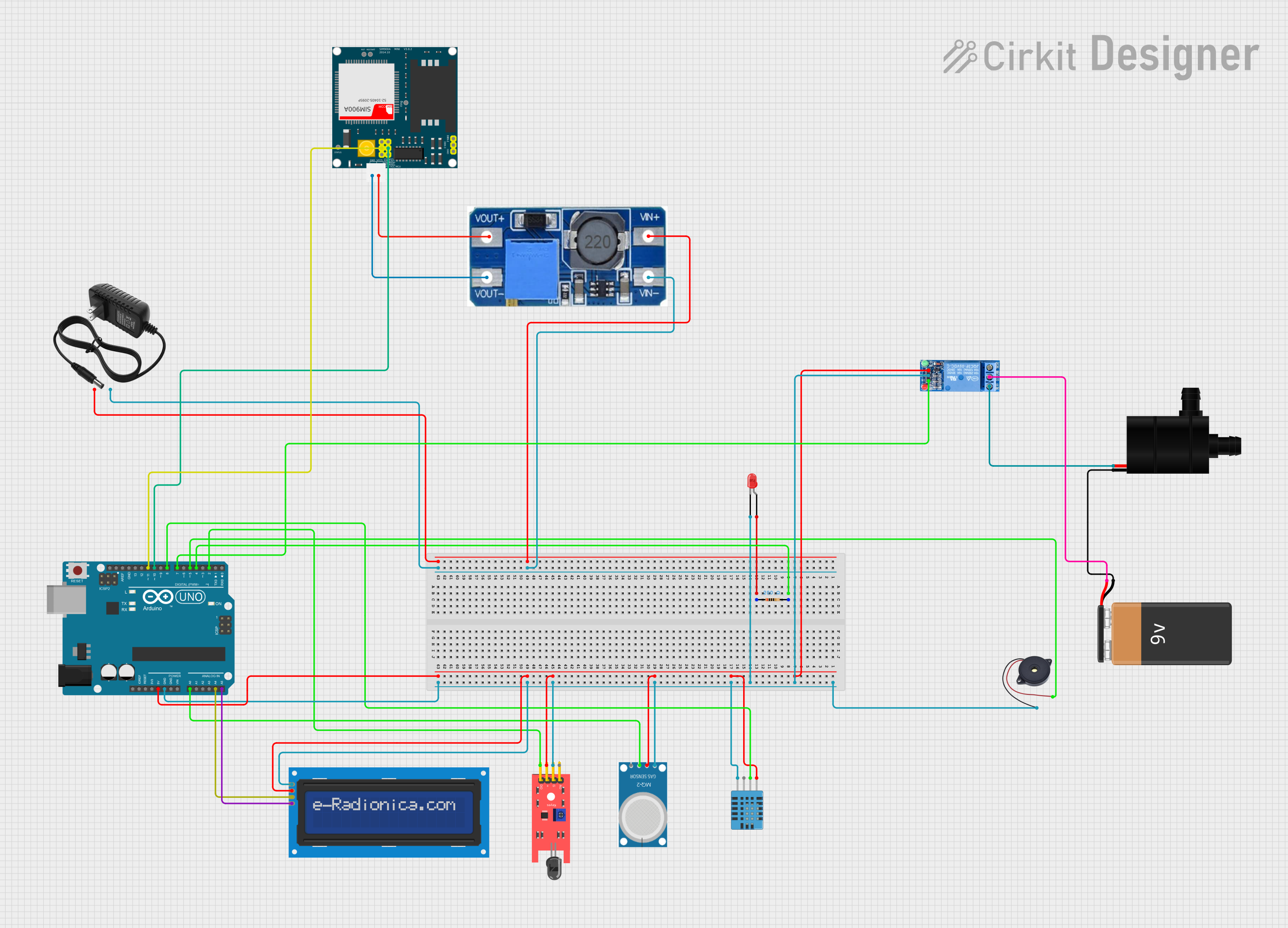
Circuit Documentation
Summary
This circuit is designed to detect fire and smoke, and respond by activating alarms, sprinklers, and sending notifications via SMS and calls. The system uses an Arduino UNO microcontroller to interface with various sensors and actuators, including a DHT11 humidity and temperature sensor, an MQ-2 smoke sensor, a KY-026 flame sensor, an LCD screen, a SIM900A GSM module, a relay, a buzzer, and an LED. The circuit is powered by a 12V power supply and a 9V battery.
Component List
Arduino UNO
- Description: Microcontroller board based on the ATmega328P.
- Pins: UNUSED, IOREF, Reset, 3.3V, 5V, GND, Vin, A0, A1, A2, A3, A4, A5, SCL, SDA, AREF, D13, D12, D11, D10, D9, D8, D7, D6, D5, D4, D3, D2, D1, D0
DHT11 Humidity and Temperature Sensor
- Description: Sensor for measuring humidity and temperature.
- Pins: VDD, DATA, NULL, GND
MQ-2
- Description: Gas sensor for detecting smoke.
- Pins: GND, VCC, ANALOG, Digital
LCD screen 16x2 I2C
- Description: 16x2 character LCD display with I2C interface.
- Pins: SCL, SDA, VCC, GND
SIM900A
- Description: GSM module for sending SMS and making calls.
- Pins: GND, DB9-3 (RXD), DB9-2 (TXD), 5V, 3VR, 5VR, 3VT, 5VT, VCC, Ring, RESTART, RESET, STATUS
LED: Two Pin (red)
- Description: Red LED.
- Pins: cathode, anode
Buzzer
- Description: Piezoelectric buzzer.
- Pins: GND, IN
1 Channel Relay 5V
- Description: Relay module for controlling high voltage devices.
- Pins: VCC, GND, IN, NC, COM, NO
Water Pump
- Description: Pump for water sprinkling.
- Pins: VCC, GND
KY-026 Flame Sensor
- Description: Sensor for detecting flame.
- Pins: A0, GND, VCC, D0
Resistor
- Description: 200 Ohms resistor.
- Pins: pin1, pin2
12V Power Supply
- Description: Power supply providing 12V.
- Pins: +, -
Step Up Boost Power Converter, Adjustable Voltage Regulator
- Description: Voltage regulator for stepping up voltage.
- Pins: VOUT+, VOUT-, VIN+, VIN-
9V Battery
- Description: Battery providing 9V.
- Pins: -, +
Wiring Details
Arduino UNO
- D4 connected to Resistor pin2
- A0 connected to MQ-2 ANALOG
- A4 connected to LCD screen 16x2 I2C SDA
- A5 connected to LCD screen 16x2 I2C SCL
- D11 connected to SIM900A 5VR
- D10 connected to SIM900A 5VT
- D8 connected to DHT11 Humidity and Temperature Sensor DATA
- D7 connected to 1 Channel Relay 5V IN
- D5 connected to Buzzer IN
- D2 connected to KY-026 Flame Sensor D0
- 5V connected to 1 Channel Relay 5V VCC, DHT11 Humidity and Temperature Sensor VDD, MQ-2 VCC, KY-026 Flame Sensor VCC, LCD screen 16x2 I2C VCC
- GND connected to Buzzer GND, 1 Channel Relay 5V GND, LED: Two Pin (red) cathode, DHT11 Humidity and Temperature Sensor GND, MQ-2 GND, KY-026 Flame Sensor GND, LCD screen 16x2 I2C GND
DHT11 Humidity and Temperature Sensor
- VDD connected to Arduino UNO 5V
- DATA connected to Arduino UNO D8
- GND connected to Arduino UNO GND
MQ-2
- GND connected to Arduino UNO GND
- VCC connected to Arduino UNO 5V
- ANALOG connected to Arduino UNO A0
LCD screen 16x2 I2C
- SCL connected to Arduino UNO A5
- SDA connected to Arduino UNO A4
- VCC connected to Arduino UNO 5V
- GND connected to Arduino UNO GND
SIM900A
- 5VR connected to Arduino UNO D11
- 5VT connected to Arduino UNO D10
- GND connected to Step Up Boost Power Converter, Adjustable Voltage Regulator VOUT-
- 5V connected to Step Up Boost Power Converter, Adjustable Voltage Regulator VOUT+
LED: Two Pin (red)
- cathode connected to Arduino UNO GND
- anode connected to Resistor pin1
Buzzer
- GND connected to Arduino UNO GND
- IN connected to Arduino UNO D5
1 Channel Relay 5V
- VCC connected to Arduino UNO 5V
- GND connected to Arduino UNO GND
- IN connected to Arduino UNO D7
- NC connected to Water Pump VCC
- COM connected to 9V Battery +
Water Pump
- VCC connected to 1 Channel Relay 5V NC
- GND connected to 9V Battery -
KY-026 Flame Sensor
- A0 not connected
- GND connected to Arduino UNO GND
- VCC connected to Arduino UNO 5V
- D0 connected to Arduino UNO D2
Resistor
- pin1 connected to LED: Two Pin (red) anode
- pin2 connected to Arduino UNO D4
12V Power Supply
- + connected to Step Up Boost Power Converter, Adjustable Voltage Regulator VIN+
- - connected to Step Up Boost Power Converter, Adjustable Voltage Regulator VIN-
Step Up Boost Power Converter, Adjustable Voltage Regulator
- VIN+ connected to 12V Power Supply +
- VIN- connected to 12V Power Supply -
- VOUT+ connected to SIM900A 5V
- VOUT- connected to SIM900A GND
9V Battery
- + connected to 1 Channel Relay 5V COM
- - connected to Water Pump GND
Documented Code
#include <SoftwareSerial.h>
#include <Wire.h>
#include <LiquidCrystal_I2C.h>
#include <DHT.h>

// GSM Module
#define rxdPin 10
#define txdPin 11
SoftwareSerial sim900A(rxdPin, txdPin);

// Sensors and Actuators
#define SMOKE_SENSOR_PIN A0
#define FLAME_SENSOR_PIN 2
#define DHTPIN 8
#define DHTTYPE DHT11
#define TEMP_THRESHOLD 50.0 // Maximum temperature threshold in °C
const String PHONE_NUMBERS[] = { "+639511197778" };
int led_pin = 4;
int buzzer_pin = 5;
int relay_pin = 7;
int SMOKE_THRESHOLD = 230;

// LCD
#define LCD_ADDRESS 0x27
#define LCD_COLUMNS 16
#define LCD_ROWS 2
LiquidCrystal_I2C lcd(LCD_ADDRESS, LCD_COLUMNS, LCD_ROWS);

// DHT Sensor
DHT dht(DHTPIN, DHTTYPE);

// Variables
int sms_counter = 0;
int call_counter = 0;
bool call_active = false;
unsigned long last_fire_time = 0;
unsigned long sprinkler_off_delay = 10000; // 10 seconds

void setup() {
  Serial.begin(9600);
  sim900A.begin(9600);

  // Pin modes
  pinMode(FLAME_SENSOR_PIN, INPUT);
  pinMode(led_pin, OUTPUT);
  pinMode(buzzer_pin, OUTPUT);
  pinMode(relay_pin, OUTPUT);

  // Initialize LCD
  lcd.init();
  lcd.backlight();