
Raspberry Pi 4B and DRV8825 Stepper Motor Controller with AS5600 Magnetic Encoder
View and Edit Project In Cirkit Designer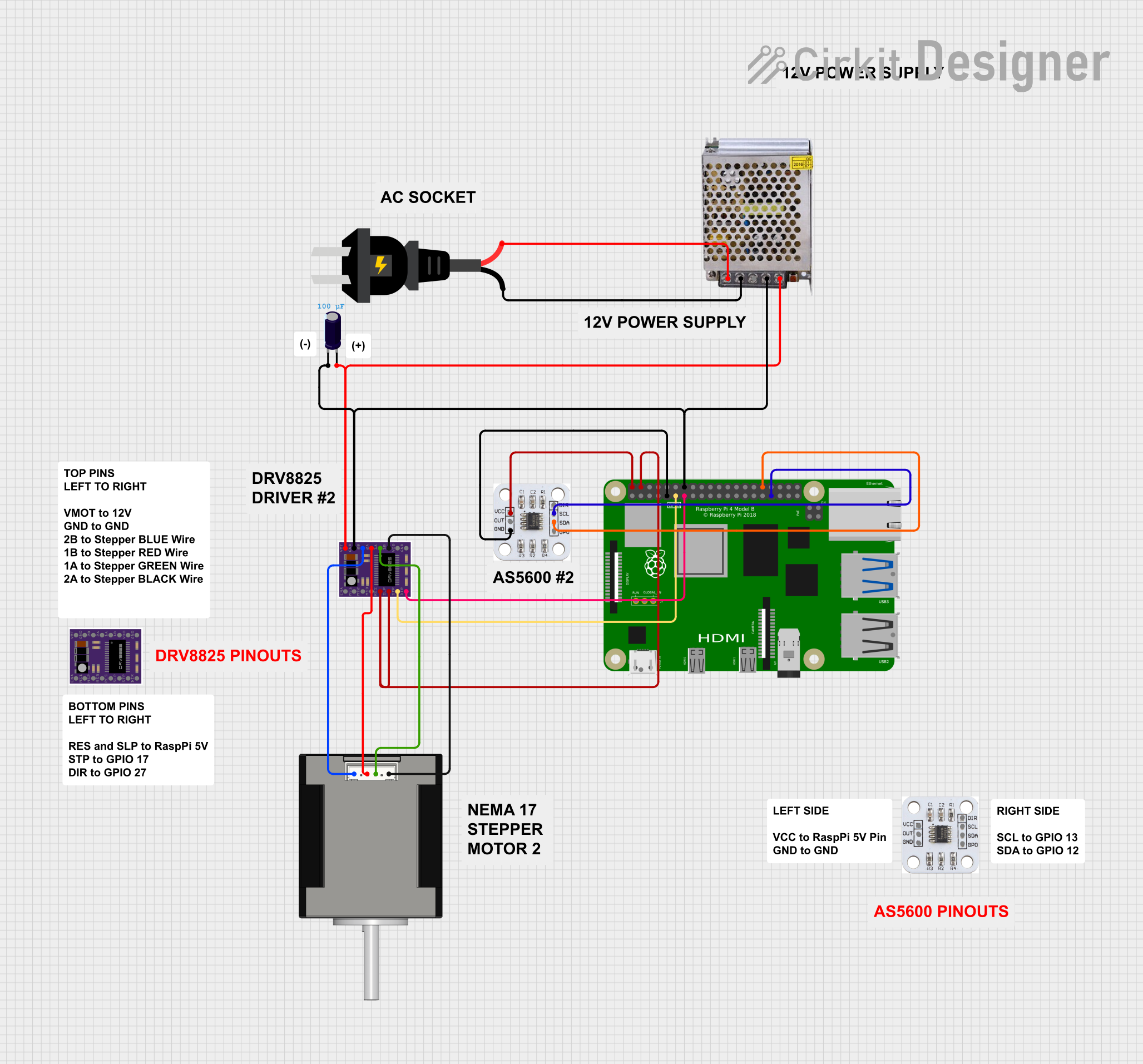
Circuit Documentation
Summary
This document provides a detailed overview of a circuit designed to control a stepper motor using a DRV8825 driver, a Raspberry Pi 4B, and an AS5600 magnetic encoder. The circuit is powered by a 12V 5A power supply and includes an electrolytic capacitor for voltage stabilization. The Raspberry Pi 4B serves as the main controller, interfacing with the DRV8825 driver and the AS5600 encoder to control the stepper motor.
Component List
DRV8825
- Description: Stepper motor driver
- Pins: ENABLE, MS1, MS2, MS3, RESET, SLEEP, STEP, DIR, GND, FAULT, 1B, 1A, 2A, 2B, VMOT
POWER SUPPLY 12V 5AMP
- Description: Power supply unit
- Pins: 220V Positive Pole (AC), 220V Negative Pole (AC), GND, GND (DC), 12V-24V Output (DC)
Electrolytic Capacitor
- Description: Capacitor for voltage stabilization
- Pins: -, +
- Properties:
- Capacitance: 0.0001 Farads
AS5600 Magnetic Encoder
- Description: Magnetic encoder for position sensing
- Pins: DIR, SCL, SDA, GP0, VCC, OUT, GND
Raspberry Pi 4B
- Description: Single-board computer
- Pins: 3V3, 5V, GPIO2, GPIO3, GND, GPIO4, GPIO14, GPIO15, GPIO17, GPIO18, GPIO27, GPIO22, GPIO23, GPIO24, GPIO10, GPIO9, GPIO25, GPIO11, GPIO8, GPIO7, ID_SD, GPIO5, GPIO6, GPIO12, GPIO13, GPIO19, GPIO16, GPIO26, GPIO20, GPIO21, ID_SC, TR01_TAP, TR00_TAP, TR03_TAP, TR02_TAP, RUN, GLOBAL_EN
Nema 17 42-STH48
- Description: Stepper motor
- Pins: A2 (black), A1 Green, B2 Red, B1 Blue
AC Source
- Description: AC power source
- Pins: +, -
Wiring Details
DRV8825
- RESET connected to SLEEP and 5V of Raspberry Pi 4B
- SLEEP connected to RESET and 5V of Raspberry Pi 4B
- STEP connected to GPIO17 of Raspberry Pi 4B
- DIR connected to GPIO27 of Raspberry Pi 4B
- GND connected to GND (DC) of POWER SUPPLY 12V 5AMP, GND of Raspberry Pi 4B, and - of Electrolytic Capacitor
- VMOT connected to 12V-24V Output (DC) of POWER SUPPLY 12V 5AMP and + of Electrolytic Capacitor
- 1B connected to A2 (black) of Nema 17 42-STH48
- 1A connected to A1 Green of Nema 17 42-STH48
- 2A connected to B2 Red of Nema 17 42-STH48
- 2B connected to B1 Blue of Nema 17 42-STH48
POWER SUPPLY 12V 5AMP
- 220V Positive Pole (AC) connected to + of AC Source
- 220V Negative Pole (AC) connected to - of AC Source
- GND (DC) connected to GND of DRV8825, GND of Raspberry Pi 4B, and - of Electrolytic Capacitor
- 12V-24V Output (DC) connected to VMOT of DRV8825 and + of Electrolytic Capacitor
Electrolytic Capacitor
- - connected to GND (DC) of POWER SUPPLY 12V 5AMP, GND of DRV8825, and GND of Raspberry Pi 4B
- + connected to 12V-24V Output (DC) of POWER SUPPLY 12V 5AMP and VMOT of DRV8825
AS5600 Magnetic Encoder
- VCC connected to 5V of Raspberry Pi 4B
- GND connected to GND of Raspberry Pi 4B
- SDA connected to GPIO12 of Raspberry Pi 4B
- SCL connected to GPIO13 of Raspberry Pi 4B
Raspberry Pi 4B
- 5V connected to VCC of AS5600 Magnetic Encoder, RESET and SLEEP of DRV8825
- GND connected to GND of AS5600 Magnetic Encoder, GND of DRV8825, GND (DC) of POWER SUPPLY 12V 5AMP, and - of Electrolytic Capacitor
- GPIO17 connected to STEP of DRV8825
- GPIO27 connected to DIR of DRV8825
- GPIO12 connected to SDA of AS5600 Magnetic Encoder
- GPIO13 connected to SCL of AS5600 Magnetic Encoder
Nema 17 42-STH48
- A2 (black) connected to 1B of DRV8825
- A1 Green connected to 1A of DRV8825
- B2 Red connected to 2A of DRV8825
- B1 Blue connected to 2B of DRV8825
AC Source
- + connected to 220V Positive Pole (AC) of POWER SUPPLY 12V 5AMP
- - connected to 220V Negative Pole (AC) of POWER SUPPLY 12V 5AMP
Code
No code is provided for this circuit.