Raspberry Pi 4B Controlled Camera with Pushbutton Interface
Circuit Documentation
Summary
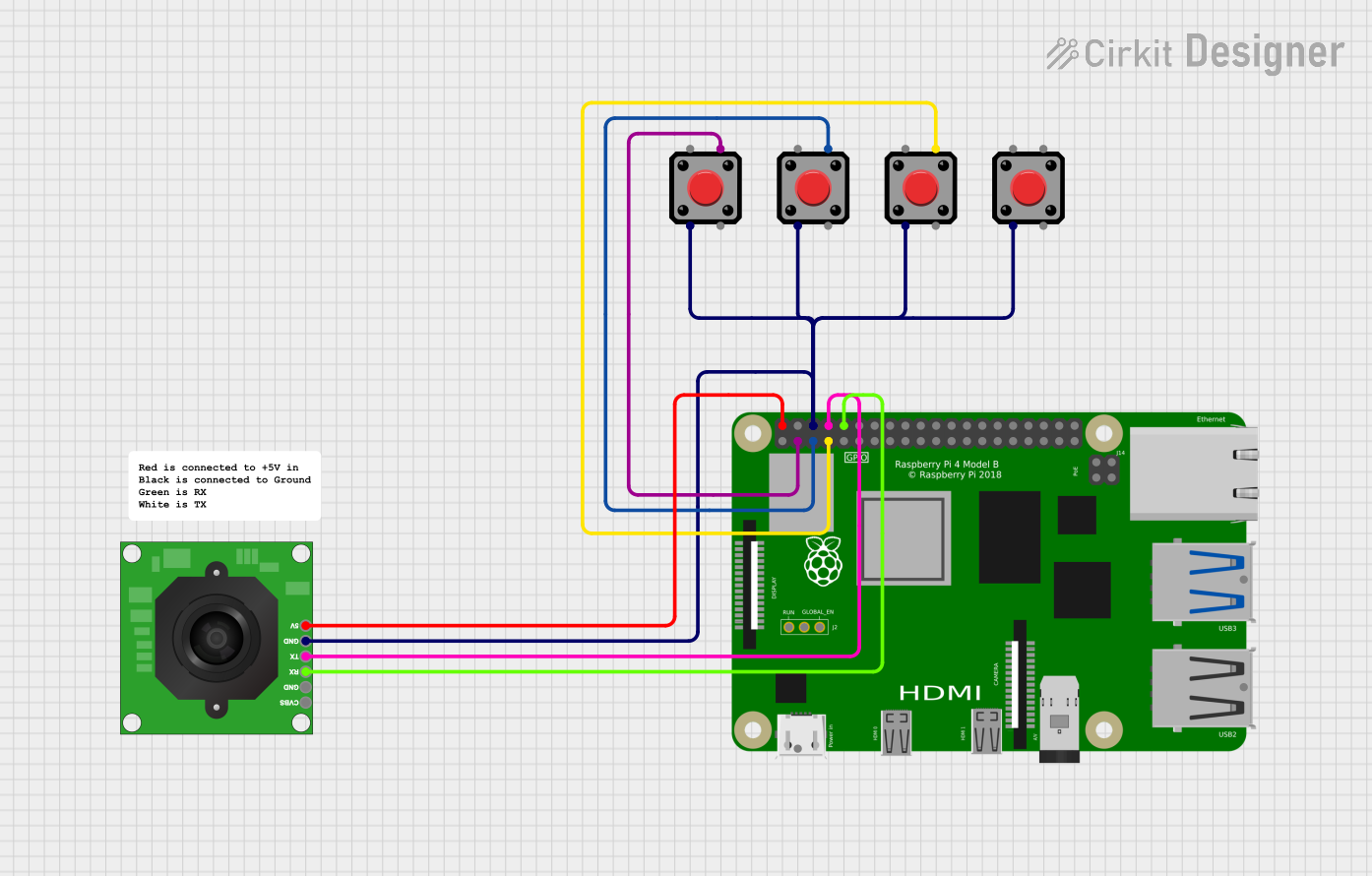
The circuit in question is designed to interface a Raspberry Pi 4B with a TTL Serial JPEG Camera and multiple pushbuttons. The Raspberry Pi 4B serves as the central processing unit, controlling the camera and reading inputs from the pushbuttons. The camera is connected to the Raspberry Pi via serial communication, and the pushbuttons are connected to GPIO pins for input detection. The 5V and GND pins on the Raspberry Pi provide power to the camera and a common ground for the entire circuit.
Component List
Raspberry Pi 4B
- Description: A powerful microcomputer with multiple GPIO pins for interfacing with various peripherals.
- Pins: 3V3, 5V, multiple GPIOs, GND, and others for specific functions.
Pushbutton
- Description: A simple switch mechanism for control or input.
- Pins: Pin 1, Pin 2, Pin 3, Pin 4.
TTL Serial JPEG Camera
- Description: A camera module capable of capturing JPEG images, interfacing via TTL serial communication.
- Pins: GND, RX, TX, CVBS, 5V.
Comment
- Description: A placeholder for additional notes or comments within the circuit design. This component does not have physical pins or electrical function.
Wiring Details
Raspberry Pi 4B
- 5V connected to TTL Serial JPEG Camera 5V (Power supply for the camera)
- GPIO2 connected to Pushbutton (Pin 4)
- GPIO3 connected to Pushbutton (Pin 4)
- GND connected to:
- Pushbutton (Pin 2)
- TTL Serial JPEG Camera GND (Common ground)
- GPIO4 connected to Pushbutton (Pin 4)
- GPIO14 (TXD) connected to TTL Serial JPEG Camera RX (Serial data transmission to camera)
- GPIO15 (RXD) connected to TTL Serial JPEG Camera TX (Serial data reception from camera)
Pushbuttons
- Pin 2 (GND) connected to Raspberry Pi GND (Common ground for all pushbuttons)
- Pin 4 connected to Raspberry Pi GPIO2, GPIO3, or GPIO4 (Input signal to Raspberry Pi)
TTL Serial JPEG Camera
- 5V connected to Raspberry Pi 5V (Power supply from Raspberry Pi)
- GND connected to Raspberry Pi GND (Common ground)
- RX connected to Raspberry Pi GPIO14 (Serial data reception from Raspberry Pi)
- TX connected to Raspberry Pi GPIO15 (Serial data transmission to Raspberry Pi)
Documented Code
No code has been provided for the microcontrollers in the circuit. The documentation of the code would typically include setup routines, main program logic, function definitions, and comments explaining the purpose and functionality of the code blocks. Since no code is available, this section remains empty.