Cirkit Designer
Your all-in-one circuit design IDE
Home /
Project Documentation
Arduino-Controlled Solenoid Valve with Relay Switching

Circuit Documentation
Summary of the Circuit
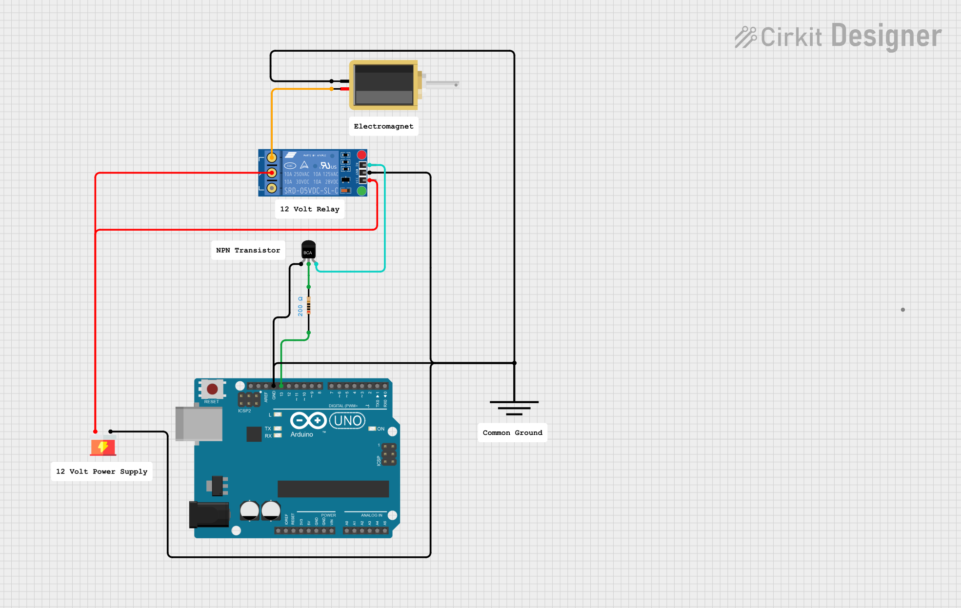
This circuit appears to be designed to control a solenoid using an Arduino UNO microcontroller. The control is facilitated through an NPN transistor and a KF-301 relay, which allows for higher current loads to be switched by the Arduino's digital output. A resistor is included, likely for current limiting purposes, and a separate power supply is used to provide power to the relay and the solenoid. Ground connections are shared among the components to complete the circuit.
Component List
Arduino UNO
- Microcontroller board based on the ATmega328P
- It has 14 digital input/output pins, 6 analog inputs, a 16 MHz quartz crystal, a USB connection, a power jack, an ICSP header, and a reset button.
NPN-Transistor
- A bipolar junction transistor used for amplification and switching purposes.
- It has three pins: Emitter (E), Collector (C), and Base (B).
Resistor
- A passive two-terminal electrical component that implements electrical resistance as a circuit element.
- Resistance: 200 Ohms
Supply
- Provides the necessary voltage and current to power the circuit.
- It has two pins: VCC and GND.
Ground
- A reference point in an electrical circuit from which voltages are measured.
- It has a single pin: GND.
Solenoid
- An electromechanical device that converts electrical energy into mechanical motion.
- It has two pins for electrical connection.
KF-301 Relay
- An electromechanical switch used to control a high-power circuit with a low-power signal.
- It has six pins: signal, power, ground, Normally Closed (NC), Common (C), and Normally Open (NO).
Wiring Details
Arduino UNO
- GND pin is connected to the common ground net.
NPN-Transistor
- Emitter (E) is connected to the common ground net.
- Collector (C) is connected to one pin of the Resistor.
- Base (B) is connected to the signal pin of the KF-301 Relay.
Resistor
- One pin is connected to the D13 pin of the Arduino UNO.
- The other pin is connected to the Collector (C) of the NPN-Transistor.
Supply
- VCC pin is connected to the power pin of the KF-301 Relay and the Common (C) pin of the relay.
- GND pin is connected to the common ground net.
Ground
- GND pin is connected to the common ground net.
Solenoid
- One pin is connected to the common ground net.
- The other pin is connected to the Normally Open (NO) pin of the KF-301 Relay.
KF-301 Relay
- Signal pin is connected to the Base (B) of the NPN-Transistor.
- Power pin is connected to the VCC pin of the Supply.
- Ground pin is connected to the common ground net.
- Common (C) pin is connected to the VCC pin of the Supply.
- Normally Open (NO) pin is connected to one pin of the Solenoid.
Documented Code
Arduino UNO Code (sketch.ino)
void setup() {
  // put your setup code here, to run once:

}

void loop() {
  // put your main code here, to run repeatedly:

}
Additional Notes (documentation.txt)
No additional code documentation was provided.