
ESP32 CAM with MLX90614 Infrared Temperature Sensor and Buzzer Notification System
View and Edit Project In Cirkit Designer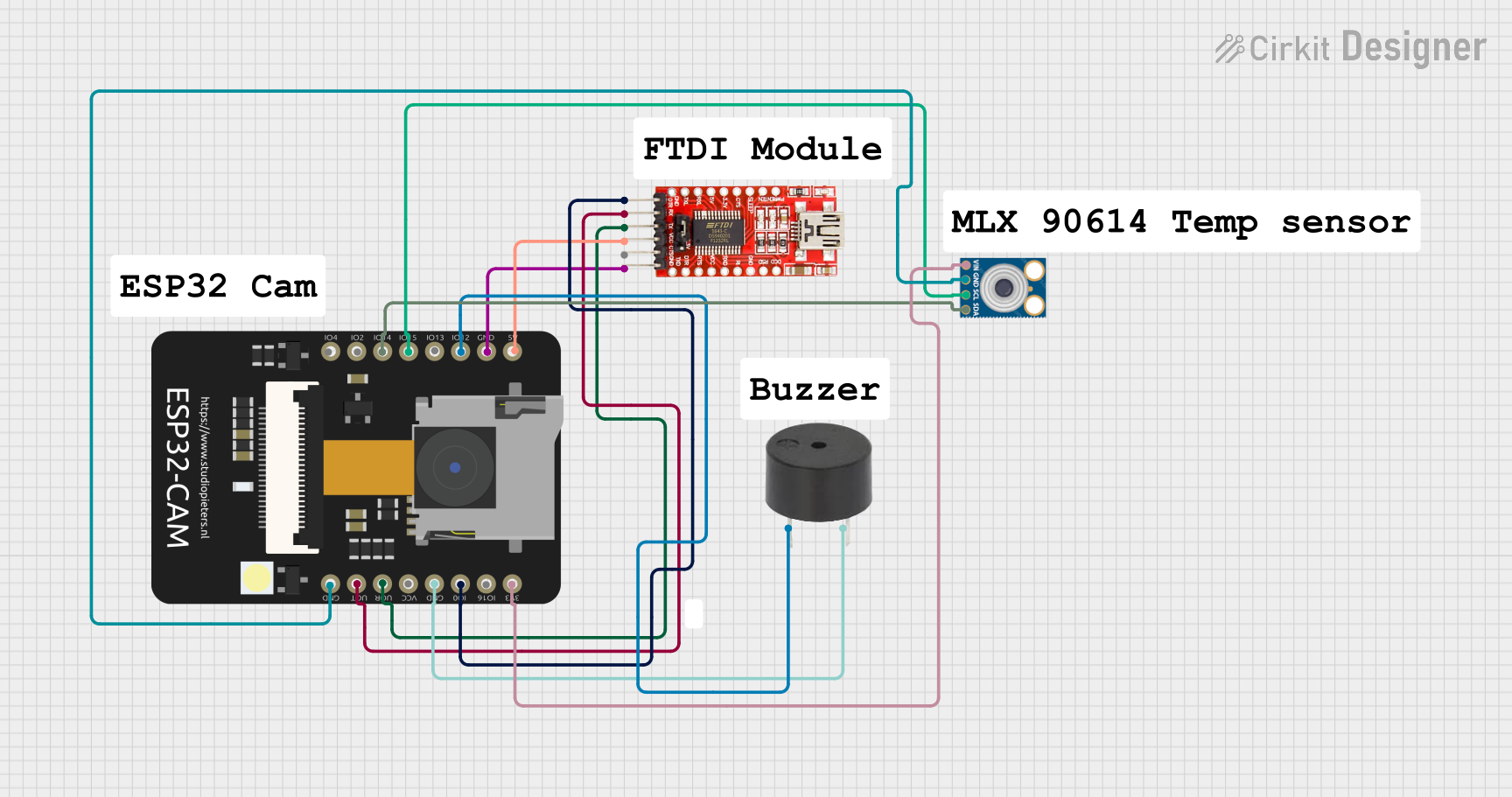
Circuit Documentation
Summary of the Circuit
This circuit integrates an ESP32 CAM module with a buzzer and an mlx90614 infrared temperature sensor, interfaced through I2C communication. The ESP32 CAM is also connected to an FTDI Programmer for programming and serial communication purposes. The circuit is designed to capture images and measure temperature, potentially for applications such as a security system with temperature monitoring capabilities.
Component List
ESP32 CAM
- Description: A small-sized ESP32-based module with Wi-Fi and camera capabilities.
- Pins: 5V, GND, GPIO12, GPIO13, GPIO15, GPIO14, GPIO2, GPIO4, 3.3V, GPIO16, GPIO0, 3.3V / 5V / P_OUT, GPIO3 / RX, GPIO1 / TX
Buzzer
- Description: An electromechanical component that produces sound when an electrical signal is applied.
- Pins: PIN, GND
FTDI Programmer
- Description: A USB to serial converter used to program microcontrollers.
- Pins: DTR, RX, TX, VCC, CTS, GND
mlx90614
- Description: An infrared thermometer for non-contact temperature measurements.
- Pins: SDA, SCL, GND, VIN
Wiring Details
ESP32 CAM
- 5V connected to FTDI Programmer VCC
- GND connected to FTDI Programmer GND, Buzzer GND, mlx90614 GND
- GPIO12 connected to Buzzer PIN
- GPIO15 (SCL) connected to mlx90614 SCL
- GPIO14 (SDA) connected to mlx90614 SDA
- 3.3V connected to mlx90614 VIN
- GPIO0 connected to FTDI Programmer DTR
- GPIO3 / RX connected to FTDI Programmer TX
- GPIO1 / TX connected to FTDI Programmer RX
Buzzer
- PIN connected to ESP32 CAM GPIO12
- GND connected to ESP32 CAM GND
FTDI Programmer
- DTR connected to ESP32 CAM GPIO0
- RX connected to ESP32 CAM GPIO1 / TX
- TX connected to ESP32 CAM GPIO3 / RX
- VCC connected to ESP32 CAM 5V
- GND connected to ESP32 CAM GND
mlx90614
- SDA connected to ESP32 CAM GPIO14
- SCL connected to ESP32 CAM GPIO15
- GND connected to ESP32 CAM GND
- VIN connected to ESP32 CAM 3.3V
Documented Code
There is no code provided for the microcontrollers in the circuit. The documentation for the code will be added once the code is available. The code would typically include initialization and configuration of the ESP32 CAM module, I2C communication setup for the mlx90614 sensor, and control logic for the buzzer based on the application requirements.