
Arduino UNO R4 WiFi-Controlled Stepper Motor with OLED Display Interface
View and Edit Project In Cirkit Designer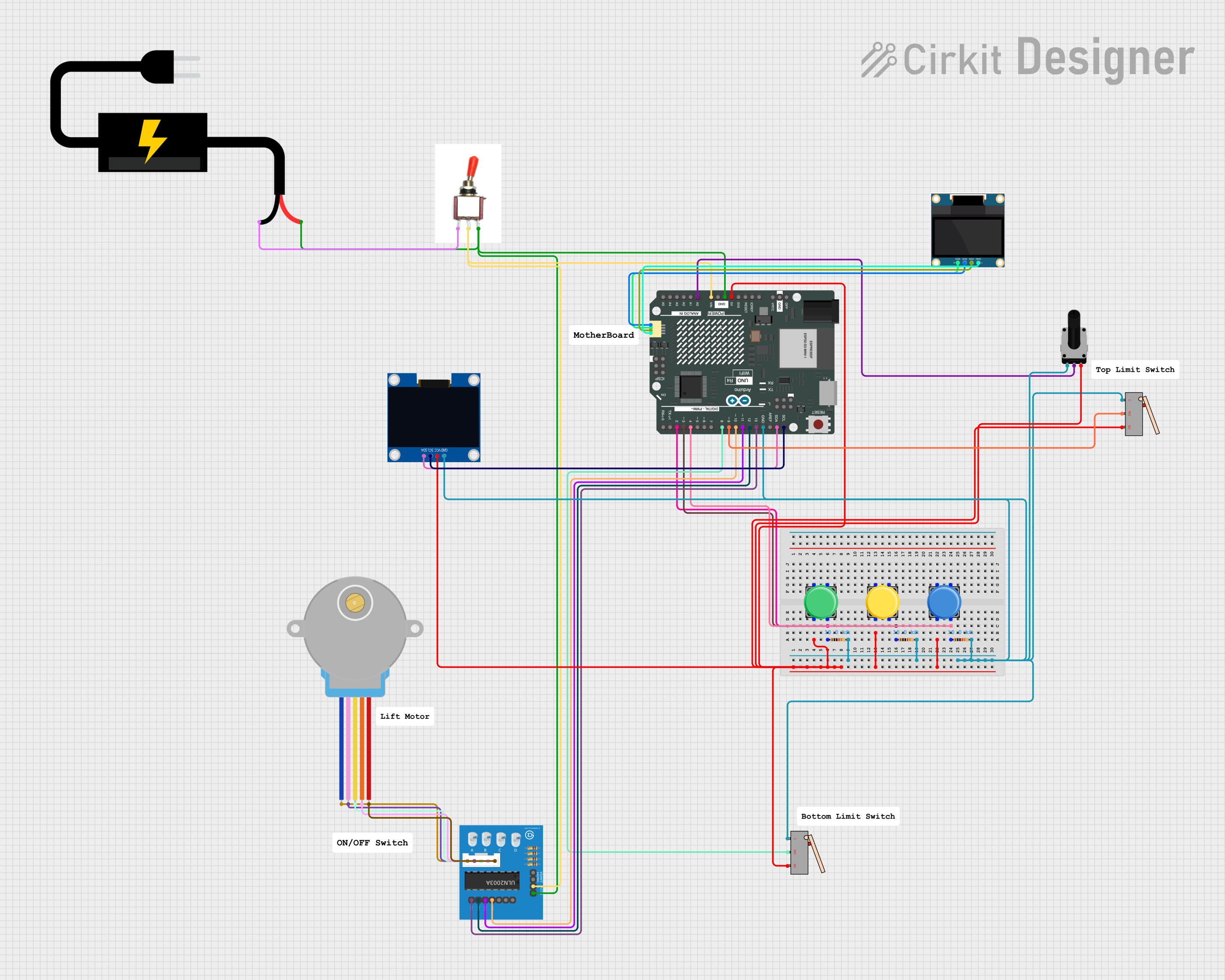
Circuit Documentation
Summary
The circuit is designed to control a 28BYJ-48 stepper motor using an Arduino UNO R4 WiFi microcontroller. The control is facilitated through pushbuttons and limit switches, with feedback provided by a 128x64 OLED display. The user can navigate options on the OLED menu to select and configure the motor's direction, position, speed, and the display's brightness. The circuit also includes a rotary potentiometer to adjust the motor speed and a real-time clock (RTC) for timekeeping. The system is powered by a DC source and includes debouncing for the pushbuttons and error handling.
Component List
- Arduino UNO R4 WiFi: A microcontroller board based on the ATmega328, which includes WiFi capabilities and a variety of digital and analog I/O pins.
- Limit Switches: Mechanical switches that are actuated by the motion of a machine part or presence of an object, used to detect the end of travel for the stepper motor.
- Toggle Switch: A switch that can maintain its state either open or closed, used to control the power supply to the circuit.
- Pushbuttons: Momentary switches that allow the user to interact with the circuit, used to navigate the OLED menu and control the stepper motor.
- 0.96" OLED: A small display that uses organic light-emitting diodes, connected via I2C, used to provide visual feedback and display the menu.
- Resistors (10k Ohms): Passive components used to limit current or divide voltages within the circuit.
- 28BYJ-48 Stepper Motor: A small and inexpensive stepper motor, used for precise control of angular or linear position, velocity, and acceleration.
- ULN2003A Breakout Board: A board that contains the ULN2003A stepper motor driver IC, used to amplify the control signals from the microcontroller to drive the stepper motor.
- Rotary Potentiometer (10k Ohms): A three-terminal resistor with a rotating contact that forms an adjustable voltage divider, used for adjusting the motor speed.
- DC Source: The power supply for the circuit, providing the necessary voltage and current to operate the components.
- 128x64 OLED Display (I2C IIC SPI Serial): Another small display similar to the 0.96" OLED, used for additional visual feedback.
Wiring Details
Arduino UNO R4 WiFi
- 5V: Connected to pushbuttons, rotary potentiometer, limit switches, and 128x64 OLED Display VCC.
- GND: Connected to resistors, limit switches, rotary potentiometer, toggle switch, ULN2003A breakout board, and both OLED displays.
- D2, D3, D4: Connected to pushbuttons through 10k Ohm resistors.
- D8, D9: Connected to NO pins of limit switches.
- D10, D11, D12, D13: Connected to input pins of ULN2003A breakout board to control the stepper motor.
- A0: Connected to the wiper of the rotary potentiometer.
- IIC0_SCL, IIC0_SDA: Connected to the 0.96" OLED SCK and SDA pins for I2C communication.
- SDA, SCL: Connected to the 128x64 OLED Display SDA and SCL pins for I2C communication.
- VIN: Connected to the toggle switch Sig pin and ULN2003A breakout board +5V pin.
Limit Switches
- NC: Connected to 5V.
- C: Connected to GND.
- NO: Connected to Arduino UNO R4 WiFi D8 and D9.
Toggle Switch
- Vcc: Connected to DC Source VCC.
- Sig: Connected to Arduino UNO R4 WiFi VIN.
- Gnd: Connected to GND.
Pushbuttons
- Pin 2: Connected to 5V.
- Pin 4: Connected to Arduino UNO R4 WiFi D2, D3, D4 through 10k Ohm resistors.
0.96" OLED
- GND: Connected to GND.
- VDD: Connected to Arduino UNO R4 WiFi 3V3.
- SCK: Connected to Arduino UNO R4 WiFi IIC0_SCL.
- SDA: Connected to Arduino UNO R4 WiFi IIC0_SDA.
Resistor (10k Ohms)
- pin1: Connected to pushbutton Pin 4.
- pin2: Connected to GND.
28BYJ-48 Stepper Motor
- BLUE, PINK, YELLOW, ORANGE, RED: Connected to corresponding wires on ULN2003A breakout board.
ULN2003A Breakout Board
- In 1, In 2, In 3, In 4: Connected to Arduino UNO R4 WiFi D13, D12, D11, D10.
- 0V: Connected to GND.
- +5V: Connected to toggle switch Sig pin.
- BLUE wire, PINK wire, YELLOW wire, ORANGE wire, RED wire: Connected to corresponding pins on 28BYJ-48 Stepper Motor.
Rotary Potentiometer (10k Ohms)
- leg1: Connected to GND.
- wiper: Connected to Arduino UNO R4 WiFi A0.
- leg2: Connected to 5V.
DC Source
- VCC: Connected to toggle switch Vcc.
- GND: Connected to GND.
128x64 OLED Display (I2C IIC SPI Serial)
- GND: Connected to GND.
- SDA: Connected to Arduino UNO R4 WiFi SDA.
- SCL: Connected to Arduino UNO R4 WiFi SCL.
- VCC: Connected to 5V.
Documented Code
/*
 * Arduino UNO R4 Project
 * This code controls a 28BYJ-48 stepper motor using push buttons Up,
 * Down, and Select to navigate options on 128x64 OLED menu. Menu items
 * should show direction, position, speed, brightness of display to be
 * selected and configured. It also displays the motor direction and speed
 * percentage on an OLED display using I2C via U8g2lib. Additionally, it
 * prints events to the serial monitor. If both up and select buttons are
 * pressed simultaneously, the motor will go until it reaches the top limit
 * switch. If the down and select buttons are pressed, it will go to the
 * lower limit switch. If only the up button is pressed, the motor will go
 * up until the button is released, stopping at the top limit switch. If
 * only the down button is pressed, the motor will go down until released,
 * stopping at the lower limit switch. If the select button is held down
 * for 10 seconds, the menu will be accessed. The display will feature time
 * and date displayed at all times in the top corners. Apply debouncing and
 * error handling, and print all events to serial console.
 */

#include <Wire.h>
#include <AccelStepper.h>
#include <RTClib.h>
#include <Bounce2.h>
#include <U8g2lib.h>

#define SCREEN_WIDTH 128
#define SCREEN_HEIGHT 64

// OLED display
//U8G2_SSD1306_128X64_NONAME_F_HW_I2C u8g2(U8G2_R0, U8X8_PIN_NONE);
U8G2_SSD1306_128X64_NONAME_1_HW_I2C u8g2(U8G2_R0, /* reset=*/ U8X8_PIN_NONE, /* clock=*/ 16, /* data=*/ 17);
// Stepper motor setup
AccelStepper stepper(AccelStepper::FULL4WIRE, 13, 12, 11, 10);

// Pushbutton pins
const int upButtonPin = 2;
const int downButtonPin = 4;
const int selectButtonPin = 3;

// Limit switch pins
const int upperLimitPin = 9;
const int lowerLimitPin = 8;

// Potentiometer pin
const int potPin = A0;

// RTC setup
RTC_DS3231 rtc;

// Variables
volatile int speedPercent = 0;
long position = 0;
long lastPosition = -1; // To track position changes
unsigned long selectButtonPressTime = 0;
bool menuActive = false;

// Debounce instances
Bounce upButton = Bounce();
Bounce downButton = Bounce();
Bounce selectButton = Bounce();

void setup() {
  // Initialize serial communication
  Serial.begin(9600);

  // Initialize display
  u8g2.begin();

  // Initialize pushbuttons with debounce
  upButton.attach(upButtonPin, INPUT_PULLDOWN);
  upButton.interval(25);
  downButton.attach(downButtonPin, INPUT_PULLDOWN);
  downButton.interval(25);
  selectButton.attach(selectButtonPin, INPUT_PULLDOWN);
  selectButton.interval(25);

  // Initialize limit switches
  pinMode(upperLimitPin, INPUT);
  pinMode(lowerLimitPin, INPUT);

  // Initialize potentiometer
  pinMode(potPin, INPUT);

  // Initialize stepper motor
  stepper.setMaxSpeed(1000);
  stepper.setAcceleration(500);

  // Initialize RTC
  if (!rtc.begin()) {
    Serial.println(F("Couldn't