Arduino UNO and MAX31865 RTD Sensor Temperature Monitoring System with Dual Piezo Buzzers
Circuit Documentation
Summary
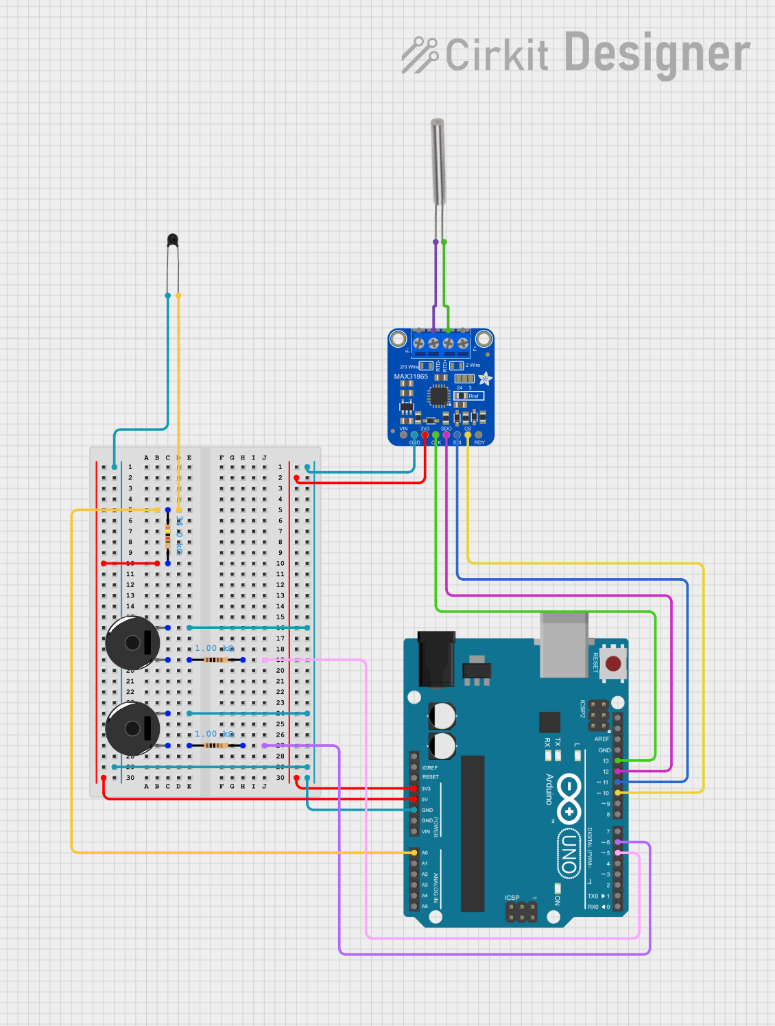
This circuit involves an Arduino UNO microcontroller interfacing with various sensors and components, including an Adafruit MAX31865 RTD Sensor Breakout, an NTC thermistor, resistors, piezo buzzers, and an RTD PT100 sensor. The circuit is designed to read temperature data from the sensors and potentially trigger the piezo buzzers based on certain conditions.
Component List
Adafruit MAX31865 RTD Sensor Breakout
- Pins: VIN, GND, 3.3V, SCLK, SDO, SDI, CS, DRDY, FORCE+, RTDIN+, RTDIN-, FORCE-
- Description: RTD-to-Digital converter for PT100 sensors.
- Purpose: To read temperature data from the RTD PT100 sensor.
Arduino UNO
- Pins: UNUSED, IOREF, Reset, 3.3V, 5V, GND, Vin, A0, A1, A2, A3, A4, A5, SCL, SDA, AREF, D13, D12, D11, D10, D9, D8, D7, D6, D5, D4, D3, D2, D1, D0
- Description: Microcontroller board based on the ATmega328P.
- Purpose: To control the circuit and process data from sensors.
NTC
- Pins: A0, A1
- Description: Negative Temperature Coefficient thermistor.
- Purpose: To measure temperature.
Resistor (34k Ohms)
- Pins: pin1, pin2
- Description: Fixed resistor.
- Purpose: To limit current or divide voltage.
Resistor (1k Ohms)
- Pins: pin1, pin2
- Description: Fixed resistor.
- Purpose: To limit current or divide voltage.
Piezo Buzzer
- Pins: pin 1, pin 2
- Description: Piezoelectric buzzer.
- Purpose: To produce sound.
RTD PT100
- Pins: 1, 2
- Description: Platinum resistance temperature detector.
- Purpose: To measure temperature.
Wiring Details
Adafruit MAX31865 RTD Sensor Breakout
- 3.3V to Arduino UNO 3.3V
- GND to Arduino UNO GND
- SCLK to Arduino UNO D13
- SDO to Arduino UNO D12
- SDI to Arduino UNO D11
- CS to Arduino UNO D10
- RTDIN+ to RTD PT100 2
- RTDIN- to RTD PT100 1
Arduino UNO
- A0 to Resistor (34k Ohms) pin1
- A0 to NTC A1
- 5V to Resistor (34k Ohms) pin2
- GND to Piezo Buzzer pin 2
- GND to NTC A0
- D5 to Resistor (1k Ohms) pin2
- D6 to Resistor (1k Ohms) pin2
NTC
- A0 to Arduino UNO GND
- A1 to Arduino UNO A0
Resistor (34k Ohms)
- pin1 to Arduino UNO A0
- pin2 to Arduino UNO 5V
Resistor (1k Ohms)
- pin1 to Piezo Buzzer pin 1
- pin2 to Arduino UNO D5
Resistor (1k Ohms)
- pin1 to Piezo Buzzer pin 1
- pin2 to Arduino UNO D6
Piezo Buzzer
- pin 1 to Resistor (1k Ohms) pin1
- pin 2 to Arduino UNO GND
RTD PT100
- 1 to Adafruit MAX31865 RTD Sensor Breakout RTDIN-
- 2 to Adafruit MAX31865 RTD Sensor Breakout RTDIN+
Code Documentation
Arduino UNO Code
void setup() {
  // put your setup code here, to run once:

}

void loop() {
  // put your main code here, to run repeatedly:

}
This code is a basic template for the Arduino UNO. The setup() function is where you initialize your components and settings, and the loop() function is where the main logic of your program runs repeatedly.
Additional Documentation
The additional documentation file is empty and can be used to add further details or instructions as needed.