Cirkit Designer
Your all-in-one circuit design IDE
Home /
Project Documentation
Arduino UNO Controlled Seven-Segment Display
Circuit Documentation
Summary
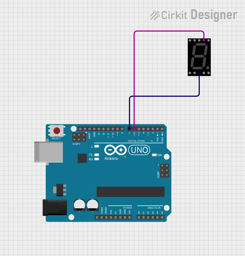
This circuit consists of an Arduino UNO microcontroller and a seven-segment display. The Arduino UNO is programmed to control the seven-segment display by setting specific pins to HIGH or LOW states.
Component List
Arduino UNO
- Description: A microcontroller board based on the ATmega328P.
- Pins: UNUSED, IOREF, Reset, 3.3V, 5V, GND, Vin, A0, A1, A2, A3, A4, A5, SCL, SDA, AREF, D13, D12, D11, D10, D9, D8, D7, D6, D5, D4, D3, D2, D1, D0
- Purpose in Circuit: To control the seven-segment display.
Seven Segment Display (Wokwi Compatible)
- Description: A display device used to show decimal numerals.
- Pins: G, F, COM.2, B, A, E, D, COM.1, C, DP
- Purpose in Circuit: To display numbers based on the signals received from the Arduino UNO.
Wiring Details
Arduino UNO
- D7: Connected to COM.1 of the Seven Segment Display
- D6: Connected to A of the Seven Segment Display
Seven Segment Display (Wokwi Compatible)
- COM.1: Connected to D7 of the Arduino UNO
- A: Connected to D6 of the Arduino UNO
Code Documentation
/*
 * This Arduino sketch controls a seven-segment display.
 * It sets pin D7 to HIGH and pin D6 to LOW.
 */

void setup() {
  // Initialize digital pin D7 as an output.
  pinMode(7, OUTPUT);
  // Initialize digital pin D6 as an output.
  pinMode(6, OUTPUT);

  // Set D7 to HIGH
  digitalWrite(7, HIGH);
  // Set D6 to LOW
  digitalWrite(6, LOW);
}

void loop() {
  // No repeated actions needed in the loop.
}
Code Explanation
- setup(): This function runs once when the Arduino is powered on or reset. It initializes pins D7 and D6 as outputs and sets D7 to HIGH and D6 to LOW.
- loop(): This function runs repeatedly after the setup function. In this case, it is empty because no repeated actions are needed.