
Arduino UNO-Based Smart Home Automation System with Real-Time Monitoring
View and Edit Project In Cirkit Designer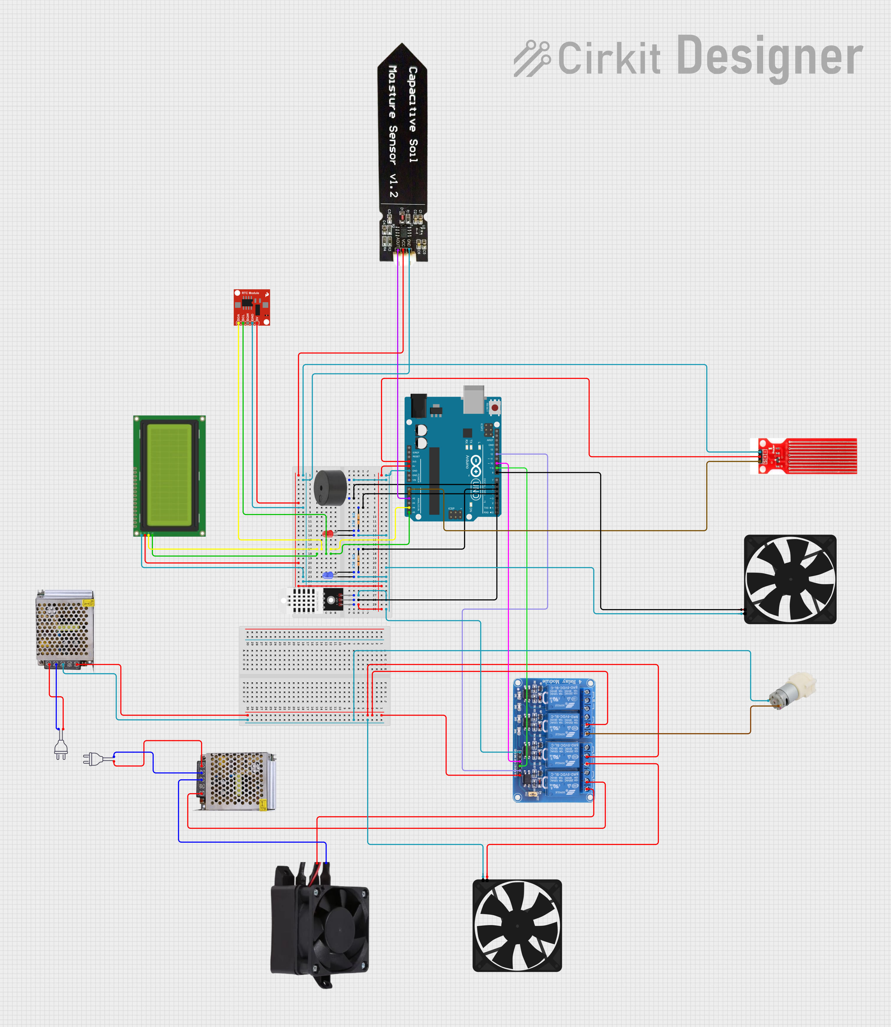
Circuit Documentation
Summary
This circuit is a comprehensive system that integrates various sensors, actuators, and display components controlled by an Arduino UNO. The system includes LEDs, a fan, a fan heater, a water pump, a soil moisture sensor, a water sensor, a buzzer, an LCD display, a real-time clock module, and a relay module. The circuit is powered by a 12V power supply and a 220V AC power source.
Component List
LED: Two Pin (red)
- Pins: cathode, anode
- Description: Red LED for visual indication.
LED: Two Pin (blue)
- Pins: cathode, anode
- Description: Blue LED for visual indication.
Fan
- Pins: GND, 5V
- Description: Fan for air circulation.
Fan Heater 12V
- Pins: Ground, 12V
- Description: Heater for temperature control.
Resistor (330k Ohms)
- Pins: pin1, pin2
- Description: Resistor for current limiting.
LCD 20x4 I2C
- Pins: GND, 5V, SCA, SCL
- Description: LCD display for visual output.
Capacitive Soil Moisture Sensor V1.2
- Pins: GND, VCC, AOUT
- Description: Sensor for measuring soil moisture.
Water Pump 12V
- Pins: +, -
- Description: Pump for water circulation.
Water Sensor
- Pins: Signal, VCC, GND
- Description: Sensor for detecting water presence.
Power Supply 12V 5AMP
- Pins: 220V Positive Pole (AC), 220V Negative Pole (AC), GND, GND (DC), 12V-24V Output (DC)
- Description: Power supply for the circuit.
Power 220V
- Pins: hot wire, neutral wire
- Description: 220V AC power source.
Arduino UNO
- Pins: UNUSED, IOREF, Reset, 3.3V, 5V, GND, Vin, A0, A1, A2, A3, A4, A5, SCL, SDA, AREF, D13, D12, D11, D10, D9, D8, D7, D6, D5, D4, D3, D2, D1, D0
- Description: Microcontroller for controlling the circuit.
Buzzer
- Pins: PIN, GND
- Description: Buzzer for audio alerts.
DHT22
- Pins: +, Out, -
- Description: Temperature and humidity sensor.
Relay 4 Channel 5V
- Pins: GND, IN1, IN2, IN3, IN4, VCC, COM1, COM2, COM3, COM4, NO1, NO2, NO3, NO4, NC1, NC2, NC3, NC4
- Description: Relay module for switching high power devices.
Real Time Clock Module - DS1307 RTC Breakout Board
- Pins: 5V, GND, SQW, SCL, SDA
- Description: Real-time clock module for timekeeping.
Wiring Details
LED: Two Pin (red)
- cathode: Connected to GND.
- anode: Connected to pin1 of a 330k Ohm resistor.
LED: Two Pin (blue)
- cathode: Connected to GND.
- anode: Connected to pin1 of a 330k Ohm resistor.
Fan
- GND: Connected to GND.
- 5V: Connected to D8 of Arduino UNO.
Fan Heater 12V
- Ground: Connected to GND of the 12V power supply.
- 12V: Connected to NO4 of the relay module.
Resistor (330k Ohms)
- pin1: Connected to anode of the respective LED.
- pin2: Connected to D4 (for red LED) and D5 (for blue LED) of Arduino UNO.
LCD 20x4 I2C
- GND: Connected to GND.
- 5V: Connected to 5V.
- SCA: Connected to A4 of Arduino UNO.
- SCL: Connected to A5 of Arduino UNO.
Capacitive Soil Moisture Sensor V1.2
- GND: Connected to GND.
- VCC: Connected to 5V.
- AOUT: Connected to A2 of Arduino UNO.
Water Pump 12V
- +: Connected to NO2 of the relay module.
- -: Connected to GND of the 12V power supply.
Water Sensor
- Signal: Connected to A1 of Arduino UNO.
- VCC: Connected to 3.3V.
- GND: Connected to GND.
Power Supply 12V 5AMP
- 220V Positive Pole (AC): Connected to hot wire of 220V power source.
- 220V Negative Pole (AC): Connected to neutral wire of 220V power source.
- GND: Connected to GND.
- GND (DC): Connected to GND.
- 12V-24V Output (DC): Connected to VCC of the relay module.
Power 220V
- hot wire: Connected to 220V Positive Pole (AC) of the power supply.
- neutral wire: Connected to 220V Negative Pole (AC) of the power supply.
Arduino UNO
- GND: Connected to GND.
- 5V: Connected to 5V.
- 3.3V: Connected to VCC of the water sensor.
- D3: Connected to Out of DHT22.
- D4: Connected to pin2 of the 330k Ohm resistor (red LED).
- D5: Connected to pin2 of the 330k Ohm resistor (blue LED).
- D6: Connected to PIN of the buzzer.
- D8: Connected to 5V of the fan.
- D9: Connected to IN3 of the relay module.
- D10: Connected to IN2 of the relay module.
- D12: Connected to IN4 of the relay module.
- A1: Connected to Signal of the water sensor.
- A2: Connected to AOUT of the soil moisture sensor.
- A4: Connected to SDA of the RTC module and SCA of the LCD.
- A5: Connected to SCL of the RTC module and SCL of the LCD.
Buzzer
- PIN: Connected to D6 of Arduino UNO.
- GND: Connected to GND.
DHT22
- +: Connected to 5V.
- Out: Connected to D3 of Arduino UNO.
- -: Connected to GND.
Relay 4 Channel 5V
- GND: Connected to GND.
- VCC: Connected to 12V-24V Output (DC) of the power supply.
- IN2: Connected to D10 of Arduino UNO.
- IN3: Connected to D9 of Arduino UNO.
- IN4: Connected to D12 of Arduino UNO.
- COM2: Connected to 12V-24V Output (DC) of the power supply.
- COM3: Connected to 12V-24V Output (DC) of the power supply.
- NO2: Connected to + of the water pump.
- NO3: Connected to 5V of the fan.
- NO4: Connected to 12V of the fan heater.
Real Time Clock Module - DS1307 RTC Breakout Board
- 5V: Connected to 5V.
- GND: Connected to GND.
- SDA: Connected to A4 of Arduino UNO.
- SCL: Connected to A5 of Arduino UNO.
Code Documentation
Arduino UNO Code
void setup() {
  // put your setup code here, to run once:

}

void loop() {
  // put your main code here, to run repeatedly:

}
This code is a basic template for the Arduino UNO. The setup() function is where you initialize your components and settings, and the loop() function is where you place the main logic that runs repeatedly.