
Arduino 101-Based Obstacle Avoidance Robot with Ultrasonic Sensor and Bluetooth Control
View and Edit Project In Cirkit Designer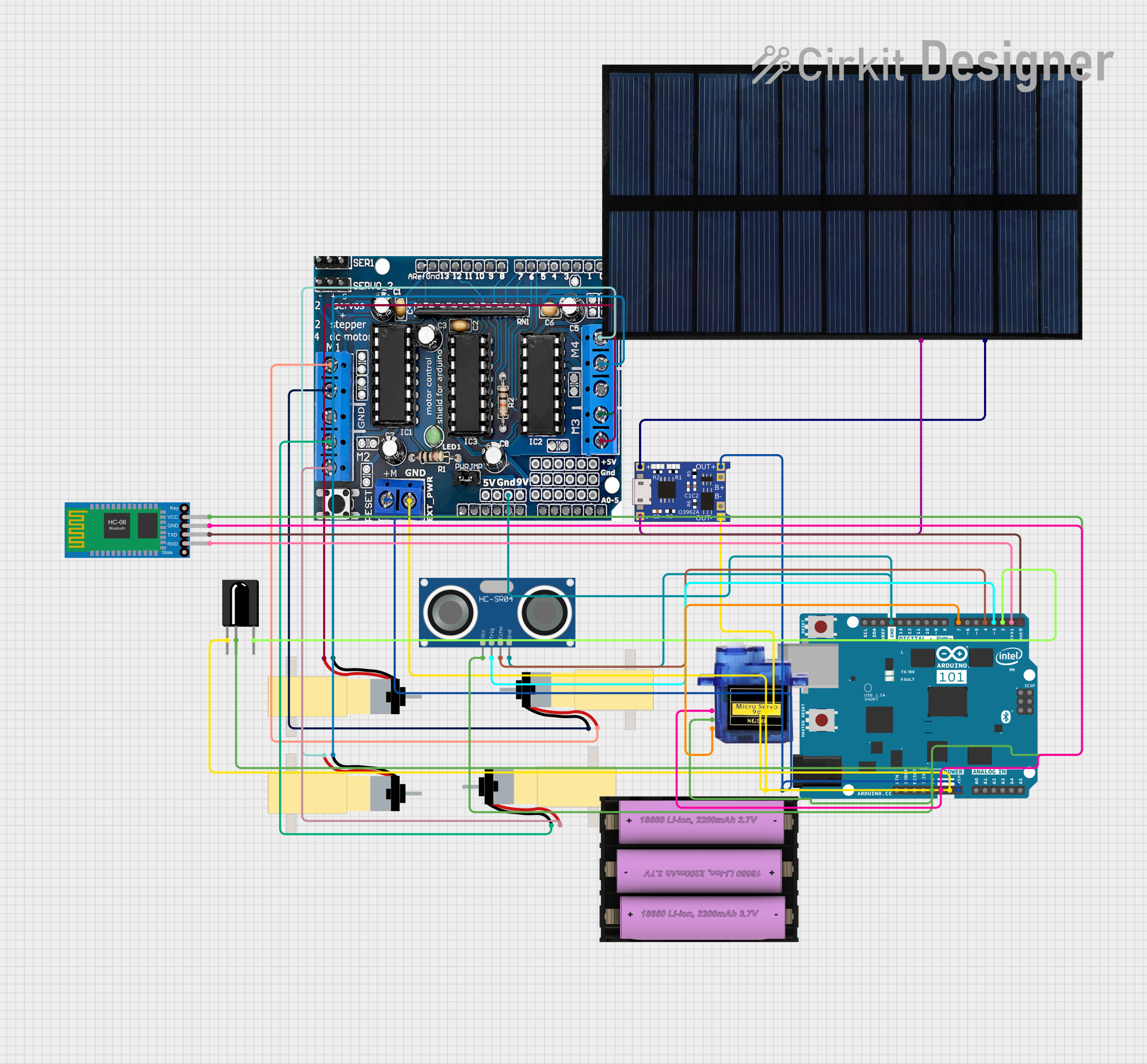
Circuit Documentation
Summary
This document provides a detailed overview of a circuit that includes an Arduino 101 microcontroller, an HC-SR04 Ultrasonic Sensor, a TSOP312 IR Receiver, a Micro Servo 9G, a Bluetooth HC-06 module, an L293D motor driver, multiple Hobby Gearmotors, a TP4056 battery charger, a set battery (7V), and a solar cell. The circuit is designed to control motors and servos, receive IR signals, and communicate via Bluetooth. It also includes a solar charging system for the battery.
Component List
HC-SR04 Ultrasonic Sensor
- Description: Ultrasonic distance sensor
- Pins: VCC, TRIG, ECHO, GND
Arduino 101
- Description: Microcontroller board
- Pins: A5/SCL, A4/SDA, AREF, GND, D13/SCK, D12/MISO, D11 PWM/MOSI, D10 PWM/SS, D9 PWM, D8, D7, D6 PWM, D5 PWM, D4, D3 PWM, D2, D1/TX, D0/RX, AIN, ioref, RESET, 3V3, 5V, VIN, A0, A1, A2, A3, ICSP MISO, ICSP SCK, ICSP MOSI
L293D
- Description: Motor driver
- Pins: 5V, GND, +, Servo1, Servo2, RX/DO, TX/D1, 9V, A0, A1, A2, A3, A4/SDA, A5/SCL, VIN, 3.3V, RESET, D2, D3, D4, D5, D6, D7, D8, D9, D10, D11, D12, D13
Hobby Gearmotor with 48:1 gearbox
- Description: Gearmotor
- Pins: pin 1, pin 2
Solar cell
- Description: Solar power source
- Pins: +, -
TP4056
- Description: Battery charger module
- Pins: OUT-, B-, B+, OUT+, IN-, IN+
Set battery (7V)
- Description: Battery
- Pins: +, -
Bluetooth HC-06
- Description: Bluetooth module
- Pins: VCC, GND, TXD, RXD
TSOP312 IR Receiver
- Description: IR receiver
- Pins: GND, Vs, Data
Micro Servo 9G
- Description: Servo motor
- Pins: GND, +5V, PWM
Wiring Details
HC-SR04 Ultrasonic Sensor
- VCC connected to Arduino 101 5V
- TRIG connected to Arduino 101 D3 PWM
- ECHO connected to Arduino 101 D4
- GND connected to Arduino 101 GND
Arduino 101
- 5V connected to HC-SR04 Ultrasonic Sensor VCC, TSOP312 IR Receiver Vs, Micro Servo 9G +5V, Bluetooth HC-06 VCC
- D3 PWM connected to HC-SR04 Ultrasonic Sensor TRIG
- D4 connected to HC-SR04 Ultrasonic Sensor ECHO
- GND connected to HC-SR04 Ultrasonic Sensor GND, L293D GND, Micro Servo 9G GND, Bluetooth HC-06 GND, TSOP312 IR Receiver GND, TP4056 OUT-, Set battery (7V) -
- D7 connected to Micro Servo 9G PWM
- D2 connected to TSOP312 IR Receiver Data
- D1/TX connected to Bluetooth HC-06 RXD
- D0/RX connected to Bluetooth HC-06 TXD
- VIN connected to TP4056 OUT+, Set battery (7V) +, L293D +
L293D
- GND connected to Arduino 101 GND, Hobby Gearmotor pin 1
- + connected to Arduino 101 VIN, Hobby Gearmotor pin 2
Hobby Gearmotor with 48:1 gearbox
- pin 1 connected to L293D GND
- pin 2 connected to L293D +
Solar cell
- + connected to TP4056 IN+
- - connected to TP4056 IN-
TP4056
- OUT- connected to Arduino 101 GND
- OUT+ connected to Arduino 101 VIN
- IN+ connected to Solar cell +
- IN- connected to Solar cell -
Set battery (7V)
- + connected to TP4056 OUT+
- - connected to TP4056 OUT-
Bluetooth HC-06
- VCC connected to Arduino 101 5V
- GND connected to Arduino 101 GND
- TXD connected to Arduino 101 D0/RX
- RXD connected to Arduino 101 D1/TX
TSOP312 IR Receiver
- Vs connected to Arduino 101 5V
- Data connected to Arduino 101 D2
- GND connected to Arduino 101 GND
Micro Servo 9G
- +5V connected to Arduino 101 5V
- PWM connected to Arduino 101 D7
- GND connected to Arduino 101 GND
Code Documentation
Arduino 101 Code
#include <AFMotor.h>
#include <IRremote.h>
#include <Servo.h>

// Pin definitions
#define IN1 5
#define IN2 6
#define IN3 9
#define IN4 10
#define ENA 3
#define ENB 11

// Motor speed
int speed = 255;  // Max speed

// Ultrasonic sensor pins
#define TRIG_PIN 3
#define ECHO_PIN 4

// Servo pin
Servo myservo;
#define SERVO_PIN 7

// IR Remote Pin
#define RECV_PIN 2

// IR receiver object
IRrecv irrecv(RECV_PIN);
decode_results results;

// Motor initialization
AF_DCMotor motor1(1);
AF_DCMotor motor2(2);
AF_DCMotor motor3(3);
AF_DCMotor motor4(4);

void setup() {
  // Serial monitor for debugging
  Serial.begin(9600);

  // Motor initialization
  motor1.setSpeed(speed);
  motor2.setSpeed(speed);
  motor3.setSpeed(speed);
  motor4.setSpeed(speed);

  // Set motor driver pins as outputs
  pinMode(IN1, OUTPUT);
  pinMode(IN2, OUTPUT);
  pinMode(IN3, OUTPUT);
  pinMode(IN4, OUTPUT);
  pinMode(ENA, OUTPUT);
  pinMode(ENB, OUTPUT);

  // Initialize the IR receiver
  irrecv.enableIRIn();

  // Initialize ultrasonic sensor
  pinMode(TRIG_PIN, OUTPUT);
  pinMode(ECHO_PIN, INPUT);

  // Initialize servo motor
  myservo.attach(SERVO_PIN);
}

void loop() {
  // Check for incoming IR signals
  if (irrecv.decode(&results)) {
    long int decCode = results.value;
    Serial.println(decCode);

    // Example: Control motors with IR remote
    if (decCode == 0xFF02FD) { // Forward
      moveForward();
    }
    else if (decCode == 0xFF03FC) { // Backward
      moveBackward();
    }
    else if (decCode == 0xFF01FE) { // Turn Left
      turnLeft();
    }
    else if (decCode == 0xFF08F7) { // Turn Right
      turnRight();
    }
    else if (decCode == 0xFF09F6) { // Stop
      stopMotors();
    }

    irrecv.resume();  // Receive the next value
  }

  // Obstacle avoidance using the servo-controlled ultrasonic sensor
  scanForObstacles();
}

// Motor Control Functions
void moveForward() {
  digitalWrite(IN1, HIGH);
  digitalWrite(IN2, LOW);
  digitalWrite(IN3, HIGH);
  digitalWrite(IN4, LOW);
  motor1.run(FORWARD);
  motor2.run(FORWARD);
  motor3.run(FORWARD);
  motor4.run(FORWARD);
}

void moveBackward() {
  digitalWrite(IN1, LOW);
  digitalWrite(IN2, HIGH);
  digitalWrite(IN3, LOW);
  digitalWrite(IN4, HIGH);
  motor1.run(BACKWARD);
  motor2.run(BACKWARD);
  motor3.run(BACKWARD);
  motor4.run(BACKWARD);
}

void turnLeft() {
  digitalWrite(IN1, LOW);
  digitalWrite(IN2, HIGH);
  digitalWrite(IN3,