
ESP32-Based Smart Home Automation System with Bluetooth Control
View and Edit Project In Cirkit Designer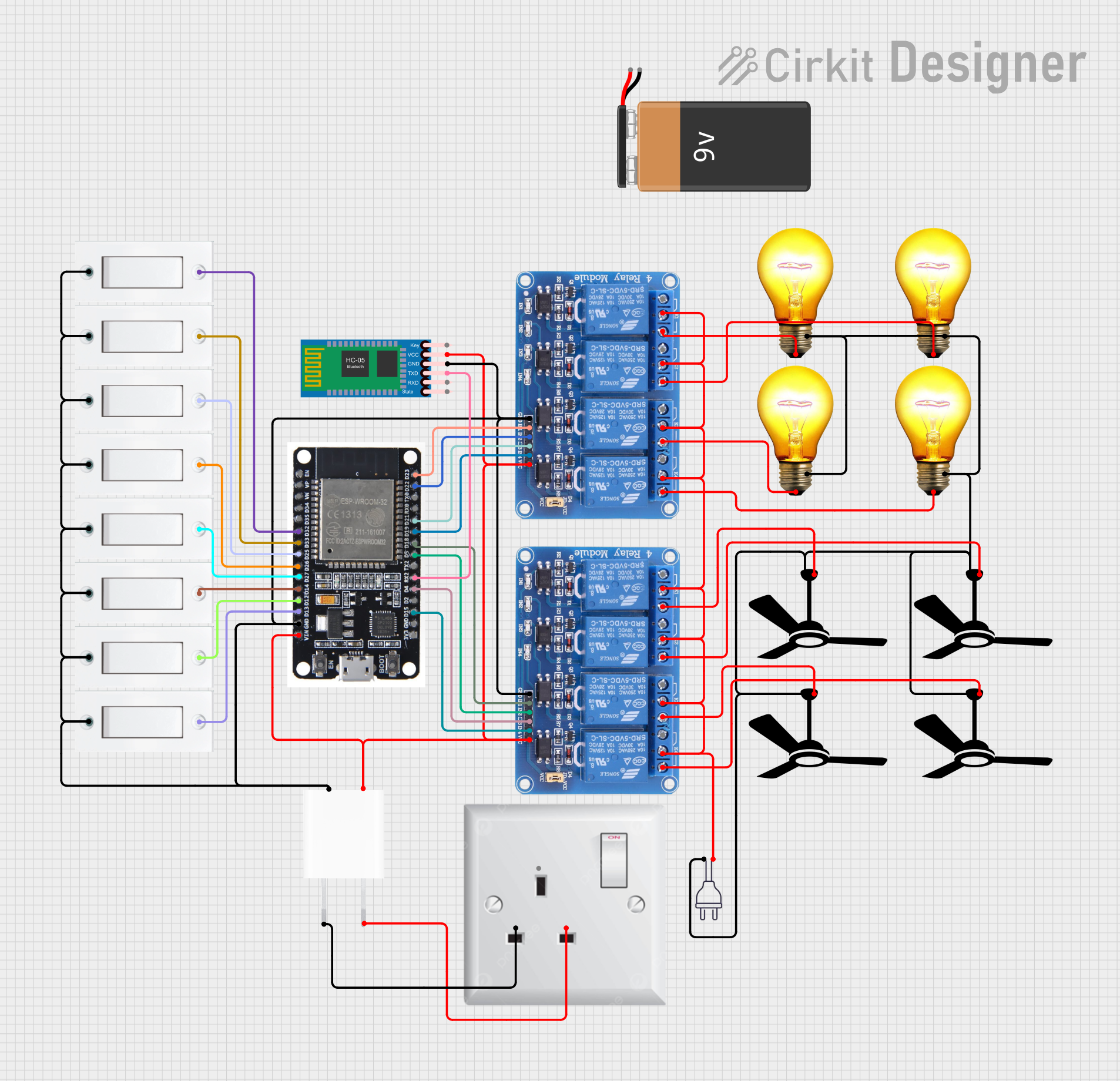
Circuit Documentation
Summary
This circuit is designed to control multiple AC bulbs and fans using an ESP32 microcontroller, a 4-channel relay module, and several flush switches. The circuit also includes an HC-05 Bluetooth module for wireless communication and a 5V adapter for power supply. The ESP32 microcontroller is programmed to control the relays based on the input from the flush switches and Bluetooth commands.
Component List
ESP32
- Description: A powerful microcontroller with built-in Wi-Fi and Bluetooth capabilities.
- Pins: EN, VP, VN, D34, D35, D32, D33, D25, D26, D27, D14, D12, D13, GND, VIN, 3V3, D15, D2, D4, RX2, TX2, D5, D18, D19, D21, RX0, TX0, D22, D23, BOOT
Relay 4 Channel 5v
- Description: A relay module used to control high voltage devices like AC bulbs and fans.
- Pins: GND, IN1, IN2, IN3, IN4, VCC, COM1, COM2, COM3, COM4, NO1, NO2, NO3, NO4, NC1, NC2, NC3, NC4
HC-05 Bluetooth Module
- Description: A Bluetooth module used for wireless communication.
- Pins: Key, VCC, TXD, RXD, State, GND
Flush Switch
- Description: A simple switch used to provide input to the microcontroller.
- Pins: GND, VCC
AC Bulb
- Description: A standard AC bulb.
- Pins: P, N
5V Adapter
- Description: A power adapter that converts AC to 5V DC.
- Pins: AC In 1, AC In 2, 5V, GND
AC Wall Plug Point
- Description: A standard AC wall plug point.
- Pins: E, N, L
Fan
- Description: A standard AC fan.
- Pins: Neutral, Live
Power 220V
- Description: A 220V power source.
- Pins: hot wire, neutral wire
9V Battery
- Description: A standard 9V battery.
- Pins: -, +
Wiring Details
ESP32
- D32 connected to Flush Switch VCC
- D33 connected to Flush Switch VCC
- D25 connected to Flush Switch VCC
- D26 connected to Flush Switch VCC
- D27 connected to Flush Switch VCC
- D14 connected to Flush Switch VCC
- D12 connected to Flush Switch VCC
- D13 connected to Flush Switch VCC
- GND connected to Flush Switch GND, Relay 4 Channel 5v GND, HC-05 Bluetooth Module GND, 5V Adapter GND
- VIN connected to 5V Adapter 5V
- D15 connected to Relay 4 Channel 5v IN4
- D4 connected to Relay 4 Channel 5v IN3
- RX2 connected to HC-05 Bluetooth Module TXD
- D5 connected to Relay 4 Channel 5v IN2
- D18 connected to Relay 4 Channel 5v IN1
- D19 connected to Relay 4 Channel 5v IN4
- D21 connected to Relay 4 Channel 5v IN3
- D22 connected to Relay 4 Channel 5v IN2
- D23 connected to Relay 4 Channel 5v IN1
Relay 4 Channel 5v
- GND connected to ESP32 GND, 5V Adapter GND
- VCC connected to 5V Adapter 5V
- IN1 connected to ESP32 D18
- IN2 connected to ESP32 D5
- IN3 connected to ESP32 D4
- IN4 connected to ESP32 D15
- COM1, COM2, COM3, COM4 connected to Power 220V hot wire
- NO1 connected to Fan Live
- NO2 connected to Fan Live
- NO3 connected to Fan Live
- NO4 connected to Fan Live
- NO1 connected to AC Bulb P
- NO2 connected to AC Bulb P
- NO3 connected to AC Bulb P
- NO4 connected to AC Bulb P
HC-05 Bluetooth Module
- GND connected to ESP32 GND
- VCC connected to 5V Adapter 5V
- TXD connected to ESP32 RX2
Flush Switch
- GND connected to ESP32 GND
- VCC connected to ESP32 D32, D33, D25, D26, D27, D14, D12, D13
AC Bulb
- P connected to Relay 4 Channel 5v NO1, NO2, NO3, NO4
- N connected to Power 220V neutral wire
5V Adapter
- AC In 1 connected to AC Wall Plug Point L
- AC In 2 connected to AC Wall Plug Point N
- 5V connected to ESP32 VIN, Relay 4 Channel 5v VCC, HC-05 Bluetooth Module VCC
- GND connected to ESP32 GND, Relay 4 Channel 5v GND, HC-05 Bluetooth Module GND
AC Wall Plug Point
- L connected to 5V Adapter AC In 1
- N connected to 5V Adapter AC In 2
Fan
- Live connected to Relay 4 Channel 5v NO1, NO2, NO3, NO4
- Neutral connected to Power 220V neutral wire
Power 220V
- hot wire connected to Relay 4 Channel 5v COM1, COM2, COM3, COM4
- neutral wire connected to Fan Neutral, AC Bulb N
Documented Code
ESP32 Code
void setup() {
  // put your setup code here, to run once:

}

void loop() {
  // put your main code here, to run repeatedly:

}
5V Adapter Code
void setup() {
  // put your setup code here, to run once:

}

void loop() {
  // put your main code here, to run repeatedly:

}
This documentation provides a comprehensive overview of the circuit, including the components used, their wiring details, and the code for the microcontrollers.