
Arduino UNO-Based Smart Garden System with Ultrasonic Sensors and GSM Communication
View and Edit Project In Cirkit Designer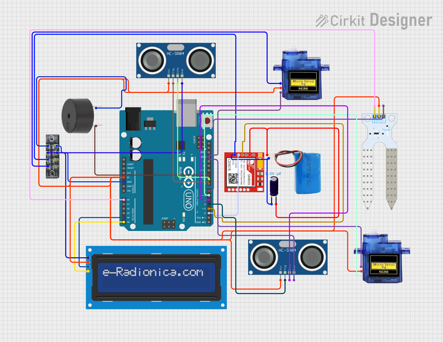
Circuit Documentation
Summary
This circuit integrates various components with an Arduino UNO microcontroller to perform a range of functions. The circuit includes sensors, actuators, a display, and communication modules. The Arduino UNO serves as the central processing unit, interfacing with an LCD screen via I2C for display, an HC-SR04 Ultrasonic Sensor for distance measurement, a buzzer for audio signaling, a SIM800L module for cellular communication, and two Micro Servo 9G motors for actuation. A soil moisture sensor is also included to monitor environmental conditions. Power distribution is managed through a 5V battery and a terminal block, with an electrolytic capacitor for voltage smoothing.
Component List
- Arduino UNO: A microcontroller board based on the ATmega328P, featuring digital and analog I/O pins.
- LCD screen 16x2 I2C: A liquid crystal display with 16 characters by 2 lines, interfaced via the I2C protocol.
- Buzzer: An audio signaling device that emits a tone when powered.
- HC-SR04 Ultrasonic Sensor: A sensor that measures distance by emitting ultrasonic waves and timing their return.
- Sim800l: A GSM/GPRS module that provides cellular communication capabilities.
- Micro servo 9G (x2): Small servo motors that can be precisely controlled through PWM signals.
- Soil Moisture Sensor: A sensor that detects the moisture level in the soil.
- Terminal Block (4 positions): A connector block used for organizing and connecting wires.
- 5V Battery: A power source providing a 5V output.
- Electrolytic Capacitor: A capacitor used for filtering and smoothing voltage fluctuations.
Wiring Details
Arduino UNO
- 5V: Powers the LCD screen, both HC-SR04 sensors, both Micro Servo 9G motors, and the Soil Moisture Sensor.
- GND: Common ground for the terminal block, Micro Servo 9G motors, HC-SR04 sensors, Soil Moisture Sensor, and the buzzer.
- A0: Connected to the signal pin of the Soil Moisture Sensor.
- A4 (SDA): Connected to the SDA pin of the LCD screen.
- A5 (SCL): Connected to the SCL pin of the LCD screen.
- D2: Connected to the TXD pin of the Sim800l module.
- D3: Connected to the RXD pin of the Sim800l module.
- D4: Connected to the TRIG pin of one HC-SR04 sensor.
- D5: Connected to the ECHO pin of one HC-SR04 sensor.
- D6: Connected to the PWM pin of one Micro Servo 9G motor.
- D7: Connected to the PWM pin of the other Micro Servo 9G motor.
- D8: Connected to the TRIG pin of the other HC-SR04 sensor.
- D9: Connected to the ECHO pin of the other HC-SR04 sensor.
- D10: Connected to the PIN pin of the buzzer.
LCD screen 16x2 I2C
- SCL: Connected to A5 (SCL) on the Arduino UNO.
- SDA: Connected to A4 (SDA) on the Arduino UNO.
- VCC: Powered by the 5V output from the Arduino UNO.
- GND: Connected to the terminal block for common ground.
Buzzer
- PIN: Connected to D10 on the Arduino UNO.
- GND: Connected to the terminal block for common ground.
HC-SR04 Ultrasonic Sensor (x2)
- VCC: Powered by the 5V output from the Arduino UNO.
- TRIG: One sensor's TRIG is connected to D4 and the other to D8 on the Arduino UNO.
- ECHO: One sensor's ECHO is connected to D5 and the other to D9 on the Arduino UNO.
- GND: Connected to the terminal block for common ground.
Sim800l
- NET: Not connected in the provided net list.
- RST: Not connected in the provided net list.
- VCC: Powered by the 5V battery through the electrolytic capacitor.
- RXD: Connected to D3 on the Arduino UNO.
- TXD: Connected to D2 on the Arduino UNO.
- GND: Connected to the terminal block for common ground.
Micro Servo 9G (x2)
- GND: Connected to the terminal block for common ground.
- +5V: Powered by the 5V output from the Arduino UNO.
- PWM: One servo's PWM is connected to D6 and the other to D7 on the Arduino UNO.
Soil Moisture Sensor
- VCC: Powered by the 5V output from the Arduino UNO.
- GND: Connected to the terminal block for common ground.
- SIG: Connected to A0 on the Arduino UNO.
Terminal Block (4 positions)
- Position 1: Connected to GND on the Arduino UNO.
- Position 2: Connected to the GND pin of the buzzer.
- Position 3: Connected to the GND pin of the LCD screen.
- Position 4: Connected to the GND pin of one HC-SR04 sensor.
- Position 6: Connected to the negative pin of the electrolytic capacitor.
- Position 8: Connected to the GND pin of one Micro Servo 9G motor.
5V Battery
- Positive: Connected to the positive pin of the electrolytic capacitor.
- Negative: Connected to the negative pin of the electrolytic capacitor and the terminal block for common ground.
Electrolytic Capacitor
- +: Connected to the positive terminal of the 5V battery.
- -: Connected to the negative terminal of the 5V battery and the terminal block for common ground.
Documented Code
Arduino UNO (sketch.ino)
void setup() {
  // put your setup code here, to run once:

}

void loop() {
  // put your main code here, to run repeatedly:

}
Note: The provided code is a template and does not include any functional code. It is expected that the user will fill in the setup and loop functions with code to control the connected components based on the wiring details provided.