
Arduino UNO-Based Temperature and Humidity Monitoring System with Data Logging
View and Edit Project In Cirkit Designer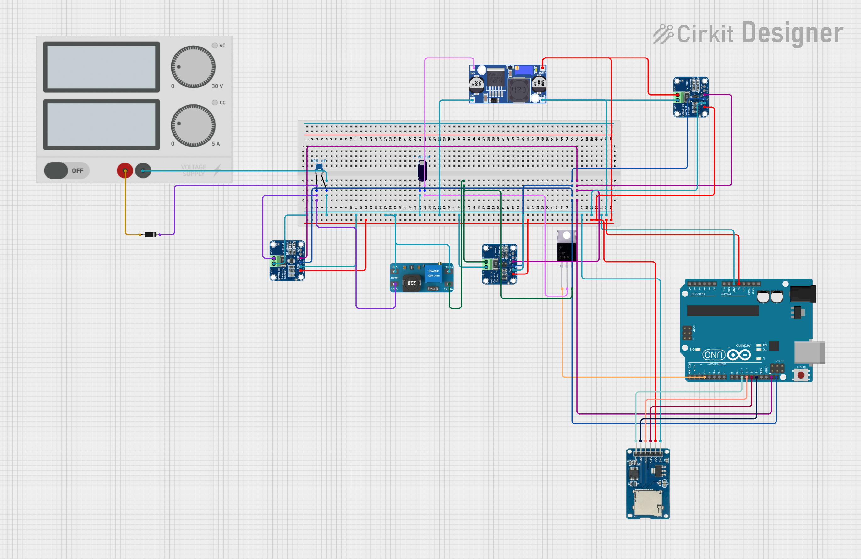
Circuit Documentation
Summary
This circuit is designed to measure temperature and humidity using an Adafruit DHT11 sensor and log the data to a Micro SD Card Module. The circuit includes various components such as an Arduino UNO, INA219 current sensors, a boost converter, a buck converter, capacitors, a diode, a MOSFET, and a power supply. The Arduino UNO is programmed to read data from the DHT11 sensor and log it to the SD card.
Component List
Diode
- Pins: Cathode, Anode
- Description: A semiconductor device that allows current to flow in one direction only.
- Purpose: Used for rectification or protection in the circuit.
Ceramic Capacitor
- Pins: Pin0, Pin1
- Description: A capacitor with a ceramic dielectric.
- Purpose: Used for filtering or decoupling in the circuit.
- Properties:
- Capacitance: 0.0000001 Farads
INA219
- Pins: VCC, GND, SCL, SDA, VIN -, VIN +
- Description: A current sensor for high-side current measurement.
- Purpose: Used to measure current and voltage in the circuit.
Arduino UNO
- Pins: UNUSED, IOREF, Reset, 3.3V, 5V, GND, Vin, A0, A1, A2, A3, A4, A5, SCL, SDA, AREF, D13, D12, D11, D10, D9, D8, D7, D6, D5, D4, D3, D2, D1, D0
- Description: A microcontroller board based on the ATmega328P.
- Purpose: Used to control the circuit and log data.
MOSFET
- Pins: Gate, Drain, Source
- Description: A type of transistor used for switching and amplification.
- Purpose: Used for switching in the circuit.
Power Supply
- Pins: +, -
- Description: Provides power to the circuit.
- Purpose: Supplies the necessary voltage and current.
Boost Converter (MT3608)
- Pins: OUTPUT +, OUTPUT -, INPUT +, INPUT -
- Description: A DC-DC converter that steps up voltage.
- Purpose: Used to increase the voltage in the circuit.
Electrolytic Capacitor
- Pins: +, -
- Description: A capacitor with an electrolyte as one of its plates.
- Purpose: Used for filtering or energy storage in the circuit.
- Properties:
- Capacitance: 0.000001 Farads
Buck Converter
- Pins: IN+, IN-, OUT+, OUT-
- Description: A DC-DC converter that steps down voltage.
- Purpose: Used to decrease the voltage in the circuit.
Micro SD Card Module
- Pins: cs, sck, mosi, miso, vcc, gnd
- Description: A module for interfacing with a micro SD card.
- Purpose: Used to log data to a micro SD card.
Wiring Details
Diode
Cathode is connected to:
- Pin0 of the Ceramic Capacitor
- VIN + of the INA219
- INPUT + of the Boost Converter
Anode is connected to:
-
- of the Power Supply
-
Ceramic Capacitor
Pin0 is connected to:
- Cathode of the Diode
- VIN + of the INA219
- INPUT + of the Boost Converter
Pin1 is connected to:
-
- of the Power Supply
-
- of the Electrolytic Capacitor
- VIN - of the INA219
- GND of the INA219
- INPUT - of the Boost Converter
- OUTPUT - of the Boost Converter
- IN- of the Buck Converter
- VIN - of another INA219
- GND of another INA219
- GND of the Micro SD Card Module
- GND of another INA219
- GND of the Arduino UNO
- OUT- of the Buck Converter
- VIN - of another INA219
-
INA219
VCC is connected to:
- VCC of another INA219
- VCC of the Micro SD Card Module
- VCC of another INA219
- 5V of the Arduino UNO
- OUT+ of the Buck Converter
- VIN + of another INA219
GND is connected to:
- Pin1 of the Ceramic Capacitor
-
- of the Electrolytic Capacitor
- VIN - of the INA219
- INPUT - of the Boost Converter
- OUTPUT - of the Boost Converter
- IN- of the Buck Converter
- VIN - of another INA219
- GND of another INA219
- GND of the Micro SD Card Module
- GND of another INA219
- GND of the Arduino UNO
- OUT- of the Buck Converter
- VIN - of another INA219
SCL is connected to:
- SCL of another INA219
- SCL of another INA219
- SCL of another INA219
- SCL of the Arduino UNO
SDA is connected to:
- SDA of another INA219
- SDA of another INA219
- SDA of another INA219
- SDA of the Arduino UNO
VIN - is connected to:
- Pin1 of the Ceramic Capacitor
-
- of the Electrolytic Capacitor
- GND of the INA219
- INPUT - of the Boost Converter
- OUTPUT - of the Boost Converter
- IN- of the Buck Converter
- VIN - of another INA219
- GND of another INA219
- GND of the Micro SD Card Module
- GND of another INA219
- GND of the Arduino UNO
- OUT- of the Buck Converter
- VIN - of another INA219
VIN + is connected to:
- Pin0 of the Ceramic Capacitor
- Cathode of the Diode
- INPUT + of the Boost Converter
Arduino UNO
5V is connected to:
- VCC of the INA219
- VCC of another INA219
- VCC of the Micro SD Card Module
- VCC of another INA219
- OUT+ of the Buck Converter
- VIN + of another INA219
GND is connected to:
- Pin1 of the Ceramic Capacitor
-
- of the Electrolytic Capacitor
- VIN - of the INA219
- GND of the INA219
- INPUT - of the Boost Converter
- OUTPUT - of the Boost Converter
- IN- of the Buck Converter
- VIN - of another INA219
- GND of another INA219
- GND of the Micro SD Card Module
- GND of another INA219
- OUT- of the Buck Converter
- VIN - of another INA219
SCL is connected to:
- SCL of the INA219
- SCL of another INA219
- SCL of another INA219
- SCL of another INA219
SDA is connected to:
- SDA of the INA219
- SDA of another INA219
- SDA of another INA219
- SDA of another INA219
D13 is connected to:
- sck of the Micro SD Card Module
D12 is connected to:
- miso of the Micro SD Card Module
D11 is connected to:
- mosi of the Micro SD Card Module
D10 is connected to:
- cs of the Micro SD Card Module
D3 is connected to:
- Gate of the MOSFET
MOSFET
Gate is connected to:
- D3 of the Arduino UNO
Drain is connected to:
-
- of the Electrolytic Capacitor
- IN+ of the Buck Converter
-
Source is connected to:
- VIN + of another INA219
- OUTPUT + of the Boost Converter
Power Supply
+ is connected to:
- Anode of the Diode
- is connected to:
- Pin1 of the Ceramic Capacitor
-
- of the Electrolytic Capacitor
- VIN - of the INA219
- GND of the INA219
- INPUT - of the Boost Converter
- OUTPUT - of the Boost Converter
- IN- of the Buck Converter
- VIN - of another INA219
- GND of another INA219
- GND of the Micro SD Card