
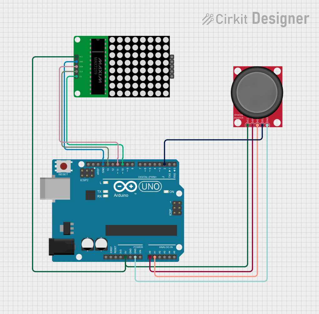
Circuit Documentation
Summary
This circuit consists of an Analog Joystick, a MAX7219 8x8 LED Matrix, and an Arduino UNO. The joystick is used to control the position of an LED on the matrix display. The Arduino UNO reads the joystick's position and button press, then updates the LED matrix accordingly.
Component List
Analog Joystick
- Description: A joystick that provides analog output for vertical and horizontal movement and a digital output for the select button.
- Pins: VCC, VERT, HORZ, SEL, GND
MAX7219 8x8 LED Matrix
- Description: An 8x8 LED matrix display controlled by the MAX7219 driver.
- Pins: CS, CLK, DIN, GND, VCC, CS(OUT), CLK(OUT), DOUT, VCC(OUT)
Arduino UNO
- Description: A microcontroller board based on the ATmega328P.
- Pins: UNUSED, IOREF, Reset, 3.3V, 5V, GND, Vin, A0, A1, A2, A3, A4, A5, SCL, SDA, AREF, D13, D12, D11, D10, D9, D8, D7, D6, D5, D4, D3, D2, D1, D0
Wiring Details
Analog Joystick
- VCC: Connected to Arduino UNO 5V
- VERT: Connected to Arduino UNO A0
- HORZ: Connected to Arduino UNO A1
- SEL: Connected to Arduino UNO D2
- GND: Connected to Arduino UNO GND
MAX7219 8x8 LED Matrix
- CS: Connected to Arduino UNO D10
- CLK: Connected to Arduino UNO D13
- DIN: Connected to Arduino UNO D11
- GND: Connected to Arduino UNO GND
- VCC: Connected to Arduino UNO 5V
Arduino UNO
- 5V: Connected to Analog Joystick VCC and MAX7219 8x8 LED Matrix VCC
- A0: Connected to Analog Joystick VERT
- A1: Connected to Analog Joystick HORZ
- D2: Connected to Analog Joystick SEL
- GND: Connected to Analog Joystick GND and MAX7219 8x8 LED Matrix GND
- D10: Connected to MAX7219 8x8 LED Matrix CS
- D13: Connected to MAX7219 8x8 LED Matrix CLK
- D11: Connected to MAX7219 8x8 LED Matrix DIN
Code Documentation
Arduino UNO Code
#include <LedControl.h>

#define CLK_PIN  13
#define DATA_PIN 11
#define CS_PIN   10

#define VERT_PIN A0
#define HORZ_PIN A1
#define SEL_PIN  2

LedControl lc = LedControl(DATA_PIN, CLK_PIN, CS_PIN, 1);

int x = 0;
int y = 0;

void setup() {
  lc.shutdown(0, false);       // Wake up displays
  lc.setIntensity(0, 8);       // Set brightness level (0 is min, 15 is max)
  lc.clearDisplay(0);          // Clear display register

  pinMode(VERT_PIN, INPUT);
  pinMode(HORZ_PIN, INPUT);
  pinMode(SEL_PIN, INPUT_PULLUP);
}

void loop() {
  int horz = analogRead(HORZ_PIN);
  int vert = analogRead(VERT_PIN);
  if (vert < 300) {
    y = min(y + 1, 7);
  }
  if (vert > 700) {
    y = max(y - 1, 0);
  }
  if (horz > 700) {
    x = min(x + 1, 7);
  }
  if (horz < 300) {
    x = max(x - 1, 0);
  }
  if (digitalRead(SEL_PIN) == LOW) {
    lc.clearDisplay(0);
  }
  lc.setLed(0, y, x, true);
  delay(100);
}
This code initializes the LED matrix and joystick, reads the joystick's position, and updates the LED matrix to reflect the joystick's position. The select button on the joystick clears the display when pressed.