Arduino-Controlled Obstacle-Avoiding Robot with Relay-Activated Water Pump
Circuit Documentation
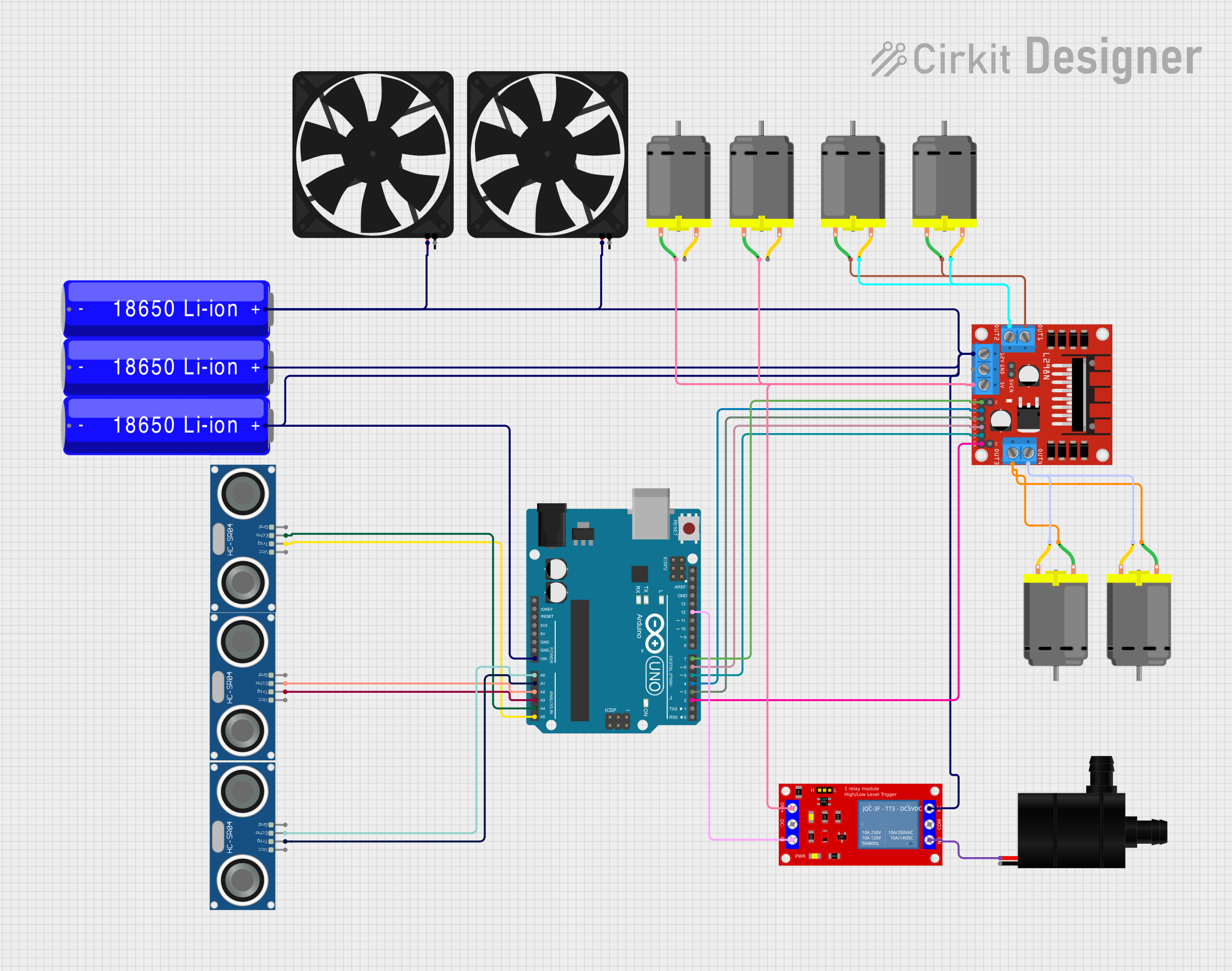
Summary of the Circuit
This circuit is designed to control various components including fans, DC motors, an ultrasonic sensor, a water pump, and a relay module using an Arduino UNO microcontroller. The power supply for the circuit is provided by multiple 18650 Li-ion batteries. The L298N DC motor driver is used to control the speed and direction of the DC motors. The HC-SR04 Ultrasonic Sensors are interfaced with the Arduino for distance measurement. The relay module is used to switch the fan and water pump on and off. The circuit appears to be part of a larger system, potentially a robotic or automated system that requires distance sensing, motor control, and actuation of a pump and cooling fans.
Component List
18650 Li-ion Battery
- Description: Rechargeable battery used to provide power to the circuit.
- Pins:
-(Negative),+(Positive)
HC-SR04 Ultrasonic Sensor
- Description: Sensor used for measuring distances via ultrasonic waves.
- Pins:
VCC(Power),TRIG(Trigger),ECHO(Echo),GND(Ground)
1 Channel 5V Relay Module
- Description: Module used for controlling high power devices such as the fan and water pump.
- Pins:
VCC+(Power),VCC- (GND)(Ground),IN(Input),N.O.(Normally Open),COM(Common),N.C.(Normally Closed)
Arduino UNO
- Description: Microcontroller board used for controlling the sensors, motors, and relay module.
- Pins: Various digital and analog I/O pins, power, and ground pins.
L298N DC Motor Driver
- Description: Module used for controlling the direction and speed of DC motors.
- Pins:
OUT1,OUT2,12V,GND,5V,OUT3,OUT4,ENA,IN1,IN2,IN3,IN4,ENB
DC Motor
- Description: Electric motor used for mechanical movements.
- Pins:
pin 1,pin 2
Fan
- Description: Cooling fan used to dissipate heat.
- Pins:
GND(Ground),5V(Power)
Water Pump
- Description: Pump used for moving water.
- Pins:
VCC(Power),GND(Ground)
Wiring Details
18650 Li-ion Battery
+connected to various components for power supply.-connected to ground.
HC-SR04 Ultrasonic Sensor
VCCconnected to 5V power supply.TRIGconnected to Arduino's analog pins for triggering distance measurement.ECHOconnected to Arduino's analog pins for receiving distance measurement.GNDconnected to ground.
1 Channel 5V Relay Module
VCC+connected to 5V power supply.VCC- (GND)connected to ground.INconnected to Arduino's digital pin for control signal.N.O.connected to Water Pump's power input.COMnot documented in the net list.N.C.connected to Fan's power input.
Arduino UNO
Vinconnected to 18650 Li-ion Battery's+pin.- Various I/O pins connected to HC-SR04 Ultrasonic Sensors, L298N DC Motor Driver, and Relay Module for control purposes.
GNDconnected to ground.
L298N DC Motor Driver
12Vconnected to 18650 Li-ion Battery's+pin for motor power supply.GNDconnected to ground.5Vconnected to DC Motor and Fan for power supply.ENA,ENBconnected to Arduino's digital pins for enabling motor driver channels.IN1,IN2,IN3,IN4connected to Arduino's digital pins for motor direction control.OUT1,OUT2,OUT3,OUT4connected to DC Motors.
DC Motor
pin 1andpin 2connected to L298N DC Motor Driver's output pins.
Fan
5Vconnected to 18650 Li-ion Battery's+pin and L298N DC Motor Driver's5Vpin for power supply.GNDconnected to ground.
Water Pump
VCCconnected to Relay Module'sN.O.pin for power control.GNDconnected to ground.
Documented Code
Arduino UNO Code (sketch.ino)
void setup() {
  // put your setup code here, to run once:

}

void loop() {
  // put your main code here, to run repeatedly:

}
Note: The provided code is a template and does not contain any functional code. It needs to be populated with the logic to control the sensors, motors, and relay module based on the requirements of the circuit's application.