
Raspberry Pi-Controlled Multi-Sensor Ultrasonic Distance Measurement System
View and Edit Project In Cirkit Designer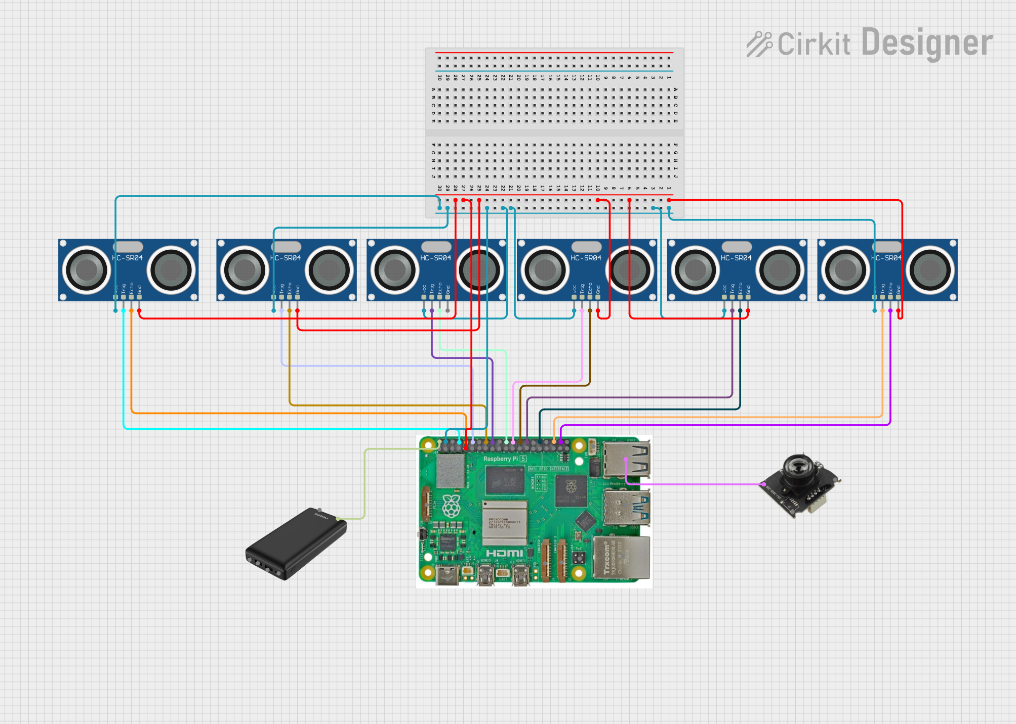
Circuit Documentation
Summary
The circuit in question is designed to interface multiple HC-SR04 Ultrasonic Sensors with a Raspberry Pi 5. The HC-SR04 sensors are used for distance measurement by emitting an ultrasonic wave and measuring the time it takes for the echo to return. The Raspberry Pi 5 serves as the central processing unit, controlling the sensors and potentially processing the data from a USB camera. The power for the circuit is provided by a power bank, ensuring a portable and independent power source.
Component List
HC-SR04 Ultrasonic Sensor
- Description: An ultrasonic distance sensor that provides 2cm to 400cm of non-contact measurement functionality with a ranging accuracy of up to 3mm.
- Pins: VCC, TRIG, ECHO, GND
Raspberry Pi 5
- Description: A small single-board computer with a broad set of I/O options, including GPIO pins, USB ports, and more.
- Pins: Type-C, Micro HDMI 1, Micro HDMI 2, Camera 1, Camera 2, PoE, Fan, PCIe, USB 3.0, USB 2.0, Ethernet, 5V, GND, 3.3v, GPIO (various)
Power Bank
- Description: A portable power supply unit for providing power to the Raspberry Pi and sensors.
USB Camera
- Description: A USB interface camera that can be connected to the Raspberry Pi for image capturing or video streaming.
Wiring Details
HC-SR04 Ultrasonic Sensors
- VCC: Connected to the 5V pin of the Raspberry Pi to supply power.
- GND: Connected to the GND pin of the Raspberry Pi to complete the power circuit.
- TRIG: Each sensor's TRIG pin is connected to a unique GPIO pin on the Raspberry Pi to trigger the distance measurement.
- ECHO: Each sensor's ECHO pin is connected to a unique GPIO pin on the Raspberry Pi to receive the reflected signal.
Raspberry Pi 5
- 5V: Supplies power to the HC-SR04 sensors.
- GND: Common ground for the HC-SR04 sensors.
- GPIO Pins: Used to interface with the TRIG and ECHO pins of the HC-SR04 sensors.
- USB 2.0: Connected to the USB camera for video input.
Power Bank
- Output: Provides 5V power to the Raspberry Pi 5.
USB Camera
- USB Interface: Connected to the USB 2.0 port of the Raspberry Pi for video input.
Documented Code
No code has been provided for the microcontrollers in the circuit. The Raspberry Pi would typically run a script or program written in Python, C++, or another suitable language to control the HC-SR04 sensors and handle data from the USB camera. The code would initialize the GPIO pins, manage the timing for sending and receiving ultrasonic pulses, calculate distances, and process the video data from the camera. Since no code is available, this section cannot be completed at this time.