Cirkit Designer
Your all-in-one circuit design IDE
Home /
Project Documentation
Arduino-Controlled Dual Motor Driver with IR Sensing
Circuit Documentation
Summary
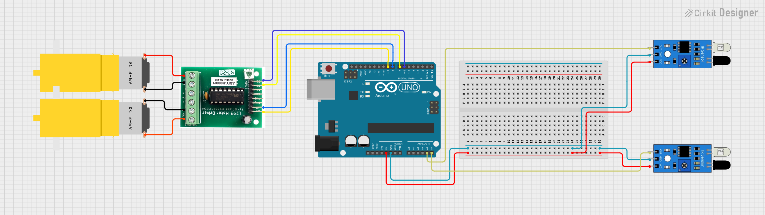
The circuit in question is designed to control two hobby motors using an Arduino UNO as the central processing unit and a motor driver to handle the power requirements of the motors. Additionally, two infrared (IR) sensors are included to provide input to the Arduino, which can be used for various sensing applications such as obstacle detection or line following.
Component List
Arduino UNO
- Description: A microcontroller board based on the ATmega328P.
- Purpose: Acts as the brain of the circuit, controlling the motor driver and reading inputs from the IR sensors.
- Pins: IOREF, Reset, 3.3V, 5V, GND, Vin, Analog (A0-A5), SCL, SDA, AREF, Digital (D0-D13).
Motor Driver
- Description: An electronic device that drives electric motors by varying the supply voltage and current to the motors.
- Purpose: To control the direction and speed of the two hobby motors.
- Pins: A1, A2, B1, B2, MA1, MA2, MB1, MB2.
IR Sensor
- Description: A sensor that emits and detects IR radiation to sense its surroundings.
- Purpose: To provide input signals to the Arduino based on IR reflection.
- Pins: out, gnd, vcc.
Motor Amarillo Motorreductor Hobby
- Description: A yellow hobby gear motor.
- Purpose: To perform mechanical work when driven by the motor driver.
- Pins: vcc, GND.
Wiring Details
Arduino UNO
- D9 connected to Motor Driver A1
- D8 connected to Motor Driver A2
- D6 connected to Motor Driver B1
- D7 connected to Motor Driver B2
- 5V connected to both IR sensors' vcc
- GND connected to both IR sensors' gnd
- A4 connected to IR sensor out (first sensor)
- A5 connected to IR sensor out (second sensor)
Motor Driver
- A1 connected to Arduino UNO D9
- A2 connected to Arduino UNO D8
- B1 connected to Arduino UNO D6
- B2 connected to Arduino UNO D7
- MA1 connected to Motor Amarillo Motorreductor Hobby vcc (first motor)
- MA2 connected to Motor Amarillo Motorreductor Hobby GND (first motor)
- MB1 connected to Motor Amarillo Motorreductor Hobby vcc (second motor)
- MB2 connected to Motor Amarillo Motorreductor Hobby GND (second motor)
IR Sensor (First Sensor)
- out connected to Arduino UNO A4
- gnd connected to Arduino UNO GND
- vcc connected to Arduino UNO 5V
IR Sensor (Second Sensor)
- out connected to Arduino UNO A5
- gnd connected to Arduino UNO GND
- vcc connected to Arduino UNO 5V
Motor Amarillo Motorreductor Hobby (First Motor)
- vcc connected to Motor Driver MA1
- GND connected to Motor Driver MA2
Motor Amarillo Motorreductor Hobby (Second Motor)
- vcc connected to Motor Driver MB1
- GND connected to Motor Driver MB2
Documented Code
Arduino UNO Code (sketch.ino)
void setup() {
  // put your setup code here, to run once:

}

void loop() {
  // put your main code here, to run repeatedly:

}
Note: The provided code is a template and does not contain any functional code to control the motors or read from the IR sensors. This will need to be implemented based on the specific requirements of the application.
Additional Files
- documentation.txt: This file is mentioned but no content is provided. It is likely intended for additional notes or manual documentation.