
Arduino Nano Controlled Humidity Sensor with RGB LED Indicator
View and Edit Project In Cirkit Designer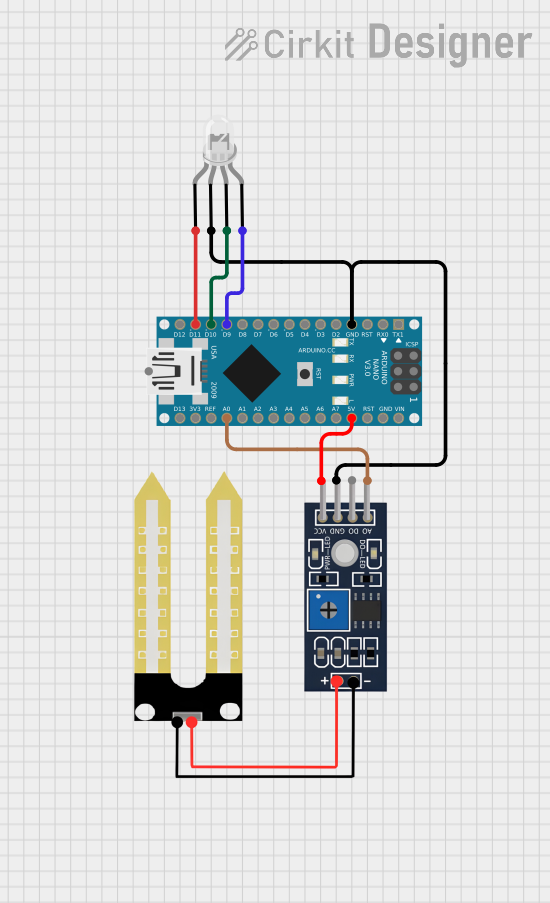
Circuit Documentation
Summary of the Circuit
This circuit consists of an Arduino Nano microcontroller, a Humidity YL-69 sensor, and a four-pin common cathode LED. The Arduino Nano serves as the central processing unit, controlling the LED based on the input from the Humidity YL-69 sensor. The LED indicates the status or the readings from the sensor. The ground pins of all components are interconnected, and the sensor's VCC pin is connected to the Arduino's 5V output to power the sensor. The sensor's analog output is connected to one of the Arduino's analog inputs for reading humidity levels. The LED's anodes are individually connected to different digital pins on the Arduino to control the color output.
Component List
Arduino Nano
- Description: A compact microcontroller board based on the ATmega328P.
- Pins: D1/TX, D0/RX, RESET, GND, D2, D3, D4, D5, D6, D7, D8, D9, D10, D11/MOSI, D12/MISO, VIN, 5V, A7, A6, A5, A4, A3, A2, A1, A0, AREF, 3V3, D13/SCK.
- Purpose: Acts as the central processing unit for the circuit, reading sensor data and controlling the LED.
Humidity YL-69 Sensor
- Description: A soil moisture sensor that can measure the humidity in the soil.
- Pins: A0, D0, GND, VCC.
- Purpose: Provides analog soil moisture level to the Arduino Nano.
LED: Four Pin (Common Cathode)
- Description: An RGB LED with a common cathode and separate anodes for red, green, and blue.
- Pins: red anode, common cathode, green anode, blue anode.
- Purpose: Displays different colors based on the signals from the Arduino Nano.
Wiring Details
Arduino Nano
- GND connected to:
- Humidity YL-69 Sensor GND
- LED common cathode
- D9 connected to LED blue anode
- D10 connected to LED green anode
- D11/MOSI connected to LED red anode
- 5V connected to Humidity YL-69 Sensor VCC
- A0 connected to Humidity YL-69 Sensor A0
Humidity YL-69 Sensor
- GND connected to Arduino Nano GND
- VCC connected to Arduino Nano 5V
- A0 connected to Arduino Nano A0
LED: Four Pin (Common Cathode)
- common cathode connected to Arduino Nano GND
- blue anode connected to Arduino Nano D9
- green anode connected to Arduino Nano D10
- red anode connected to Arduino Nano D11/MOSI
Documented Code
Arduino Nano Code (sketch.ino)
void setup() {
  // put your setup code here, to run once:

}

void loop() {
  // put your main code here, to run repeatedly:

}
Note: The provided code is a template and does not contain any functional code to interact with the Humidity YL-69 sensor or control the LED. The user is expected to fill in the setup and loop functions with the appropriate initialization and control logic.