Cirkit Designer
Your all-in-one circuit design IDE
Home /
Project Documentation
Arduino and ESP8266-Based Smart Sensor System with Ultrasonic and DHT22 Sensors
Circuit Documentation
Summary
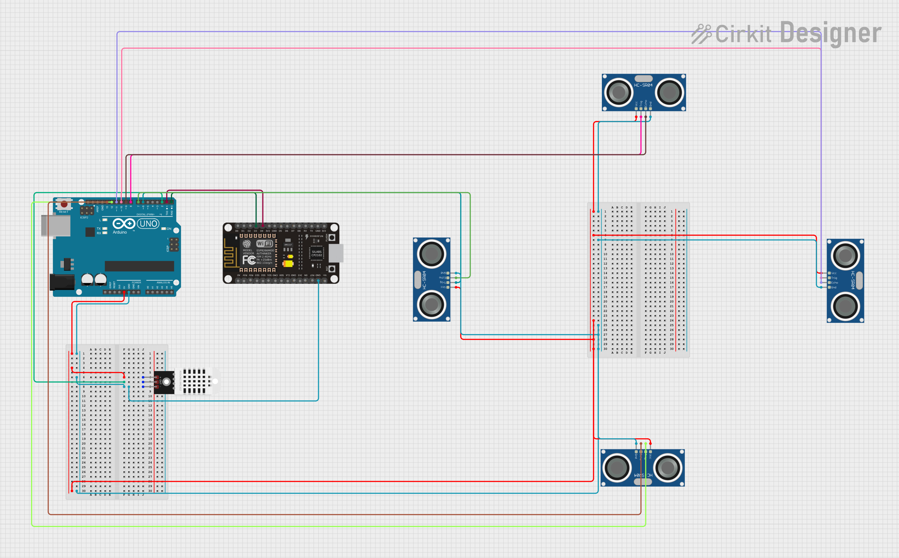
This circuit involves an Arduino UNO, an ESP8266 NodeMCU, a DHT22 temperature and humidity sensor, and four HC-SR04 ultrasonic sensors. The Arduino UNO serves as the main microcontroller, interfacing with the sensors and the ESP8266 NodeMCU for potential wireless communication. The DHT22 sensor measures temperature and humidity, while the HC-SR04 sensors measure distance using ultrasonic waves.
Component List
Arduino UNO
- Description: A microcontroller board based on the ATmega328P.
- Pins: UNUSED, IOREF, Reset, 3.3V, 5V, GND, Vin, A0, A1, A2, A3, A4, A5, SCL, SDA, AREF, D13, D12, D11, D10, D9, D8, D7, D6, D5, D4, D3, D2, D1, D0
ESP8266 NodeMCU
- Description: A low-cost Wi-Fi microchip with full TCP/IP stack and microcontroller capability.
- Pins: D0, D1, D2, D3, D4, 3V3, GND, D5, D6, D7, D8, RX, TX, A0, RSV, SD3, SD2, SD1, CMD, SD0, CLK, EN, RST, VIN
DHT22
- Description: A temperature and humidity sensor.
- Pins: +, Out, -
HC-SR04 Ultrasonic Sensor
- Description: An ultrasonic sensor for distance measurement.
- Pins: VCC, TRIG, ECHO, GND
Wiring Details
Arduino UNO
- 5V: Connected to the VCC pin of all HC-SR04 sensors and the + pin of the DHT22 sensor.
- GND: Connected to the GND pin of all HC-SR04 sensors, the - pin of the DHT22 sensor, and the GND pin of the ESP8266 NodeMCU.
- D2: Connected to the Out pin of the DHT22 sensor.
- D13: Connected to the ECHO pin of one HC-SR04 sensor.
- D12: Connected to the TRIG pin of one HC-SR04 sensor.
- D11: Connected to the ECHO pin of another HC-SR04 sensor.
- D10: Connected to the TRIG pin of another HC-SR04 sensor.
- D9: Connected to the ECHO pin of another HC-SR04 sensor.
- D8: Connected to the TRIG pin of another HC-SR04 sensor.
- D7: Connected to the ECHO pin of another HC-SR04 sensor.
- D6: Connected to the TRIG pin of another HC-SR04 sensor.
- D1: Connected to the D4 pin of the ESP8266 NodeMCU.
- D0: Connected to the D3 pin of the ESP8266 NodeMCU.
ESP8266 NodeMCU
- GND: Connected to the GND pin of the Arduino UNO and the - pin of the DHT22 sensor.
- D4: Connected to the D1 pin of the Arduino UNO.
- D3: Connected to the D0 pin of the Arduino UNO.
DHT22
- +: Connected to the 5V pin of the Arduino UNO.
- Out: Connected to the D2 pin of the Arduino UNO.
- -: Connected to the GND pin of the Arduino UNO and the ESP8266 NodeMCU.
HC-SR04 Ultrasonic Sensor
- VCC: Connected to the 5V pin of the Arduino UNO.
- GND: Connected to the GND pin of the Arduino UNO.
- TRIG: Connected to various digital pins (D12, D10, D8, D6) of the Arduino UNO.
- ECHO: Connected to various digital pins (D13, D11, D9, D7) of the Arduino UNO.
Documented Code
Arduino UNO Code (sketch.ino)
void setup() {
  // put your setup code here, to run once:

}

void loop() {
  // put your main code here, to run repeatedly:

}
Additional Documentation (documentation.txt)
This documentation provides a comprehensive overview of the circuit, including a summary, detailed component list, wiring details, and the code used in the microcontroller.