Cirkit Designer
Your all-in-one circuit design IDE
Home /
Project Documentation
ESP8266-Based Air Quality Monitoring System with OLED Display and Wi-Fi Connectivity
Circuit Documentation
Summary
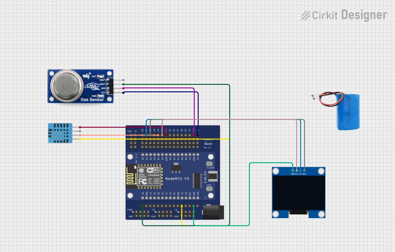
This circuit is an air quality monitoring system that uses an ESP8266 microcontroller to read data from a DHT11 humidity and temperature sensor and an MQ-135 gas sensor. The data is displayed on a 128x64 OLED display. The system is powered by a 5V battery.
Component List
ESP8266 Custom Board
- Description: A custom board based on the ESP8266 microcontroller, used for Wi-Fi connectivity and general control of the circuit.
- Pins: GND1-0, GND1-1, GND1-2, GND1-3, 3V1-0, 3V1-1, 3V1-2, 3V1-3, D0-0, D0-1, D0-2, D0-3, D1-0, D1-1, D1-2, D1-3, D2-0, D2-1, D2-2, D2-3, D3-0, D3-1, D3-2, D3-3, D4-0, D4-1, D4-2, D4-3, 3V2-0, 3V2-1, 3V2-2, 3V2-3, GND2-0, GND2-1, GND2-2, GND2-3, D5-0, D5-1, D5-2, D5-3, D6-0, D6-1, D6-2, D6-3, D7-0, D7-1, D7-2, D7-3, D8-0, D8-1, D8-2, D8-3, RX-0, RX-1, RX-2, RX-3, TX-0, TX-1, TX-2, TX-3, GND3-0, GND3-1, GND3-2, GND3-3, 3V3-0, 3V3-1, 3V3-2, 3V3-3, A0, GND4, VU, S3, S2, S1, SC, S0, SK, GND5, 3V4, EN, RST, GND6, VIN, VUSB-0, GND8-0, VUSB-1, GND8-1, VUSB-2, GND8-2, VUSB-3, GND8-3, 5V-0, GND8-4, 5V-1, GND8-5, 5V-2, GND8-6, 5V-3, GND8-7, UI-0, GND8-8, UI-1, GND8-9, UI-2, GND8-10, UI-3, GND8-11
MQ-135 Gas Sensor
- Description: A gas sensor used to measure air quality.
- Pins: D OUT, A OUT, GND, VCC
DHT11 Humidity and Temperature Sensor
- Description: A sensor used to measure humidity and temperature.
- Pins: VDD, DATA, NULL, GND
128x64 OLED Display (I2C IIC SPI Serial)
- Description: An OLED display used to show sensor data.
- Pins: GND, SDA, SCL, VCC
5V Battery
- Description: A battery used to power the circuit.
- Pins: positive, negative
Wiring Details
ESP8266 Custom Board
- D1-0: Connected to SCL of 128x64 OLED Display
- D2-0: Connected to SDA of 128x64 OLED Display
- D4-0: Connected to DATA of DHT11 Humidity and Temperature Sensor
- 3V2-0: Connected to VCC of 128x64 OLED Display
- GND2-0: Connected to GND of DHT11 Humidity and Temperature Sensor
- GND3-0: Connected to GND of MQ-135 Gas Sensor
- 3V3-0: Connected to VCC of MQ-135 Gas Sensor
- A0: Connected to A OUT of MQ-135 Gas Sensor
- 3V4: Connected to VDD of DHT11 Humidity and Temperature Sensor
- GND6: Connected to GND of 128x64 OLED Display
MQ-135 Gas Sensor
- GND: Connected to GND3-0 of ESP8266 Custom Board
- VCC: Connected to 3V3-0 of ESP8266 Custom Board
- A OUT: Connected to A0 of ESP8266 Custom Board
DHT11 Humidity and Temperature Sensor
- DATA: Connected to D4-0 of ESP8266 Custom Board
- GND: Connected to GND2-0 of ESP8266 Custom Board
- VDD: Connected to 3V4 of ESP8266 Custom Board
128x64 OLED Display (I2C IIC SPI Serial)
- SCL: Connected to D1-0 of ESP8266 Custom Board
- SDA: Connected to D2-0 of ESP8266 Custom Board
- VCC: Connected to 3V2-0 of ESP8266 Custom Board
- GND: Connected to GND6 of ESP8266 Custom Board
5V Battery
- positive: Not connected in the provided net list
- negative: Not connected in the provided net list
Code Documentation
#include <ESP8266WiFi.h>
#include <Adafruit_Sensor.h>
#include <DHT.h>
#include <Wire.h>
#include <Adafruit_SSD1306.h>

#define DHTPIN 2          // DHT11 data pin on GPIO2
#define DHTTYPE DHT11
#define MQ135_PIN A0      // MQ-135 analog output pin
#define PM_SENSOR_TX 3    // PM sensor TX pin

DHT dht(DHTPIN, DHTTYPE);
Adafruit_SSD1306 display(128, 64, &Wire, -1);

// Wi-Fi credentials
const char* ssid = "Your_SSID";
const char* password = "Your_PASSWORD";

void setup() {
  Serial.begin(9600);

  // Initialize sensors
  dht.begin();
  pinMode(MQ135_PIN, INPUT);

  // Initialize OLED display
  if (!display.begin(SSD1306_SWITCHCAPVCC, 0x3C)) {
    Serial.println("SSD1306 allocation failed!");
    for (;;);
  }
  display.clearDisplay();

  // Connect to Wi-Fi
  WiFi.begin(ssid, password);
  while (WiFi.status() != WL_CONNECTED) {
    delay(1000);
    Serial.println("Connecting to Wi-Fi...");
  }
  Serial.println("Wi-Fi connected!");
}

void loop() {
  // Read data
  float humidity = dht.readHumidity();
  float temperature = dht.readTemperature();
  int mq135Value = analogRead(MQ135_PIN);

  // Display data on OLED
  display.clearDisplay();
  display.setTextSize(1);
  display.setTextColor(WHITE);
  display.setCursor(0, 0);
  display.println("Air Quality Monitoring");
  display.print("Temp: ");
  display.print(temperature);
  display.println(" C");
  display.print("Humidity: ");
  display.print(humidity);
  display.println(" %");
  display.print("Gas PPM: ");
  display.println(mq135Value);
  display.display();

  // Send data to Serial Monitor
  Serial.print("Temperature: ");
  Serial.println(temperature);
  Serial.print("Humidity: ");
  Serial.println(humidity);
  Serial.print("MQ135 Value: ");
  Serial.println(mq135Value);

  delay(2000); // Delay 2 seconds
}
This code initializes the DHT11 sensor, MQ-135 gas sensor, and the OLED display. It connects to a Wi-Fi network and continuously reads data from the sensors, displaying it on the OLED and sending it to the Serial Monitor.