
Circuit Documentation
Summary of the Circuit
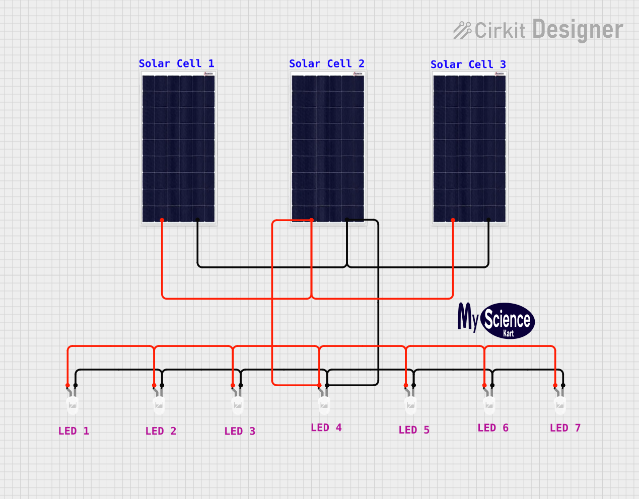
This circuit appears to be a simple solar-powered LED array. It consists of three solar cells connected in parallel, which are used to power a series of LEDs also connected in parallel. The positive terminals of the solar cells are connected to the anodes of the LEDs, and the negative terminals are connected to the cathodes, completing the circuit. There is no microcontroller or additional control logic involved, indicating that the LEDs will illuminate whenever there is sufficient light to power the solar cells.
Component List
Solar Cells
- Component Name: Solar Cell
- Description: A device that converts light into electrical energy.
- Purpose: To provide power to the LEDs when exposed to light.
- Pins:
- Positive
- Negative
LEDs
- Component Name: LED: Two Pin (white)
- Description: A light-emitting diode that produces white light.
- Purpose: To emit light when powered by the solar cells.
- Pins:
- Anode (positive side)
- Cathode (negative side)
Comments
- Component Name: Comment
- Description: Textual annotations within the circuit design for documentation or explanation purposes. These do not have a physical manifestation in the actual circuit.
Logo
- Component Name: Logo
- Description: A graphical representation or branding element within the circuit design. Like comments, this does not have a physical role in the circuit's function.
Wiring Details
Solar Cells
- Solar Cell
- Positive connected to the anodes of all LEDs.
- Negative connected to the cathodes of all LEDs.
LEDs
- LED: Two Pin (white)
- Anode connected to the positive terminals of all solar cells.
- Cathode connected to the negative terminals of all solar cells.
Documented Code
There is no embedded code provided for this circuit as it does not include any programmable components or microcontrollers. The operation of the circuit is purely based on the electrical connections and does not require any software control.