ESP32-Based Smart Soil Analysis and Environmental Monitoring System
Circuit Documentation
Summary
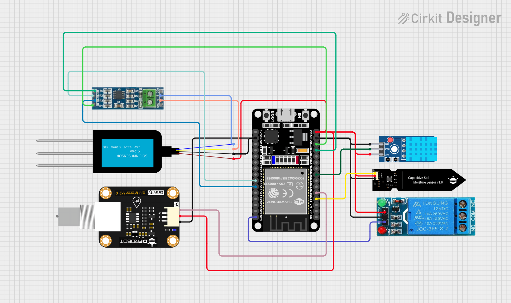
This circuit integrates a variety of sensors and modules with an ESP32 microcontroller to monitor environmental parameters such as soil moisture, temperature, humidity, and pH levels. It also includes a relay for controlling power to external devices. Communication with some sensors is facilitated by an RS-485 module, indicating a potential for long-distance sensor data acquisition. The circuit is powered through the ESP32's Vin pin, which is connected to various VCC pins on the sensors and relay, indicating a common power supply requirement.
Component List
ESP32 (30 pin)
- A microcontroller with WiFi and Bluetooth capabilities.
- It has a variety of digital and analog pins for interfacing with sensors and modules.
12V Single Channel Relay
- A relay module capable of controlling high power devices.
- It has Normally Closed (NC), Common (COM), and Normally Open (NO) terminals for switching, as well as an input (IN), ground (GND), and VCC for control.
DFRobot Capacitive Soil Moisture Sensor (V1.0)
- A sensor for measuring the moisture level in soil.
- It has an analog output (A), VCC, and GND.
DHT11 Sensor V2
- A sensor for measuring temperature and humidity.
- It has a data pin (DAT), VCC, and GND.
NPK Soil Sensor (mini)
- A sensor for measuring Nitrogen, Phosphorus, and Potassium (NPK) in soil.
- It has two analog outputs (A and B), VCC, and GND.
RS-485 Module
- A module for RS-485 communication, allowing for long-distance data transmission.
- It has VCC, A and B for differential communication, GND, and pins for receiver output (RO), receiver enable (RE), driver enable (DE), and driver input (DI).
Modulo Sensor PH
- A sensor for measuring the pH level of a solution.
- It has an analog output (A), a sensor output (SON), and power connections (+ and -).
Wiring Details
ESP32 (30 pin)
- D34 connected to DFRobot Capacitive Soil Moisture Sensor (A)
- D35 connected to Modulo Sensor PH (A)
- D25 connected to DHT11 Sensor V2 (DAT)
- D12 connected to RS-485 Module (RO)
- D13 connected to RS-485 Module (DI)
- GND connected to common ground
- Vin connected to common VCC
- D23 connected to 12V Single Channel Relay (IN)
- D19 connected to RS-485 Module (DE)
- D18 connected to RS-485 Module (RE)
12V Single Channel Relay
- IN controlled by ESP32 (D23)
- GND connected to common ground
- VCC connected to common VCC
DFRobot Capacitive Soil Moisture Sensor (V1.0)
- A connected to ESP32 (D34)
- VCC connected to common VCC
- GND connected to common ground
DHT11 Sensor V2
- DAT connected to ESP32 (D25)
- VCC connected to common VCC
- GND connected to common ground
NPK Soil Sensor (mini)
- A connected to RS-485 Module (A)
- B connected to RS-485 Module (B)
- VCC connected to common VCC
- GND connected to common ground
RS-485 Module
- A connected to NPK Soil Sensor (mini) (A)
- B connected to NPK Soil Sensor (mini) (B)
- RO connected to ESP32 (D12)
- DI connected to ESP32 (D13)
- DE controlled by ESP32 (D19)
- RE controlled by ESP32 (D18)
- VCC connected to common VCC
- GND connected to common ground
Modulo Sensor PH
- A connected to ESP32 (D35)
- connected to common VCC
- connected to common ground
Documented Code
No code was provided for the microcontrollers in the circuit. The documentation of the code would typically include descriptions of the functionality implemented, setup and loop functions for Arduino-based microcontrollers, and any libraries or external dependencies required for the code to run. It would also include comments within the code to explain the purpose of each section or function. Since no code is available, this section remains empty.