ESP32-Controlled Soil Moisture Monitoring and Water Pump System
Circuit Documentation
Summary
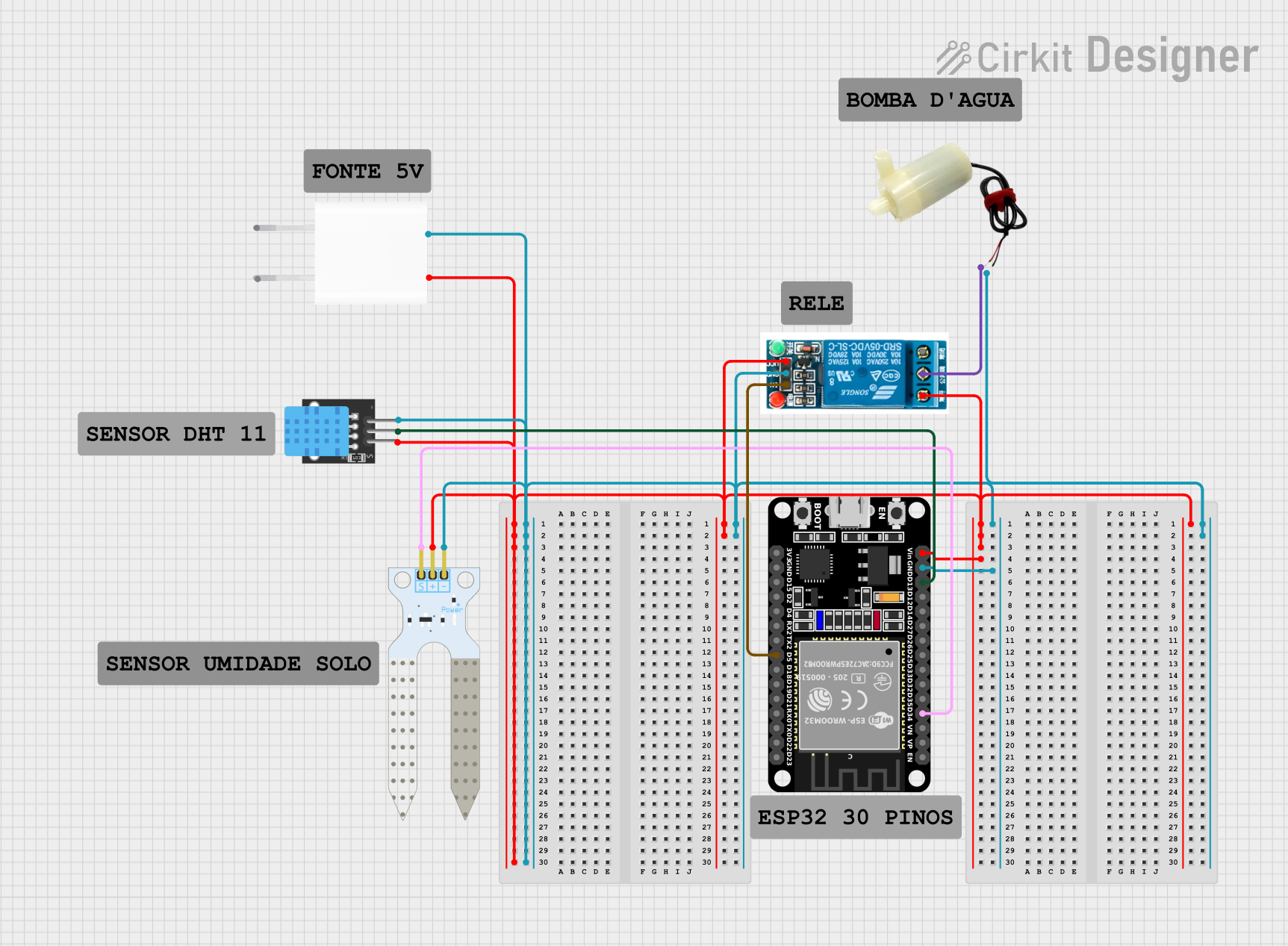
The circuit in question appears to be designed for environmental monitoring and control, likely for applications such as automated plant watering systems. It includes an ESP32 microcontroller for processing and control, a DHT11 sensor for measuring temperature and humidity, a soil moisture sensor for detecting water content in the soil, a 5V mini water pump for water delivery, a 5V relay to control the water pump, and a 5V adapter to provide power to the system.
Component List
ESP32 (30 pin)
- Description: A microcontroller with WiFi and Bluetooth capabilities, featuring a wide range of GPIO pins for interfacing with various sensors and actuators.
- Purpose: Acts as the central processing unit of the circuit, reading sensor data and controlling the relay and water pump based on programmed logic.
DHT11
- Description: A basic, low-cost digital temperature and humidity sensor.
- Purpose: Measures the ambient temperature and humidity to provide environmental data to the ESP32.
5v mini water pump
- Description: A small water pump that operates at 5V.
- Purpose: Used to deliver water to the plant when the soil moisture level is below a certain threshold.
5v relay
- Description: An electromechanical switch that allows a low-power signal to control a higher power circuit.
- Purpose: Controls the power to the water pump, allowing the ESP32 to turn the pump on and off.
5V Adapter
- Description: A power supply that converts AC mains power to 5V DC.
- Purpose: Provides the necessary power to the circuit components.
Soil Moisture Sensor
- Description: A sensor that measures the volumetric water content of the soil.
- Purpose: Provides data on soil moisture levels to the ESP32, which can then decide whether watering is needed.
Wiring Details
ESP32 (30 pin)
Vinconnected to 5V power supply.GNDconnected to the ground of the power supply.D34connected to theSIGpin of the Soil Moisture Sensor.D13connected to theSpin of the DHT11 sensor.D5connected to theInpin of the 5v relay.
DHT11
5Vconnected to 5V power supply.Sconnected toD13on the ESP32.GNDconnected to the ground of the power supply.
5v mini water pump
positive pinconnected to theCommon terminalof the 5v relay.negative pinconnected to the ground of the power supply.
5v relay
VCCconnected to 5V power supply.Normally Opennot connected in this configuration.Common terminalconnected to thepositive pinof the 5v mini water pump.Inconnected toD5on the ESP32.GNDconnected to the ground of the power supply.
5V Adapter
5Voutput connected to the 5V power rail supplying the ESP32, DHT11, Soil Moisture Sensor, and the 5v relay.GNDoutput connected to the ground rail supplying the ESP32, DHT11, Soil Moisture Sensor, 5v mini water pump, and the 5v relay.
Soil Moisture Sensor
VCCconnected to 5V power supply.GNDconnected to the ground of the power supply.SIGconnected toD34on the ESP32.
Documented Code
No code was provided for the microcontroller. The expected code should handle reading data from the DHT11 and Soil Moisture Sensor, process the data, and control the relay based on the sensor inputs to activate the water pump when necessary. The code should also include WiFi or Bluetooth functionality for remote monitoring or control, as supported by the ESP32 microcontroller.