Cirkit Designer
Your all-in-one circuit design IDE
Home /
Project Documentation
Wireless Motion-Activated Alert System with Arduino and NRF24L01
Circuit Documentation
Summary
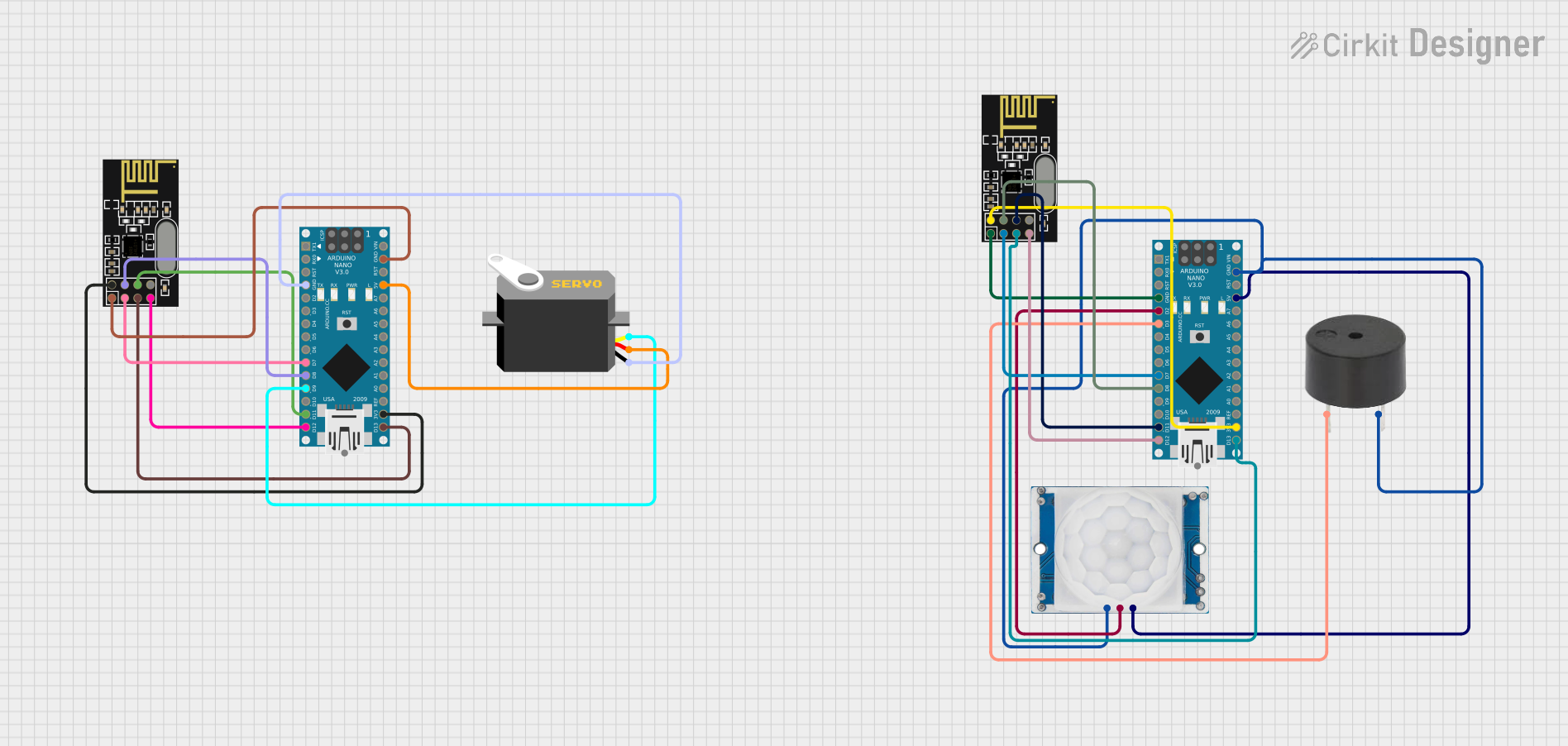
This circuit integrates various components to perform wireless communication and motion detection functionalities. It includes two Arduino Nano microcontrollers, each interfaced with an NRF24L01 wireless transceiver module. Additionally, the circuit incorporates an HC-SR501 PIR motion sensor to detect motion and a buzzer for audible alerts. A servo motor is also part of the system, which can be controlled based on signals from the microcontroller.
Component List
NRF24L01 Wireless Transceiver Module
- Description: A wireless transceiver module that operates on the 2.4 GHz band.
- Pins: IRQ (not used), MOSI, CSN, VCC (3V), GND, CE, SCK, MISO.
Arduino Nano
- Description: A small, complete, and breadboard-friendly board based on the ATmega328P.
- Pins: D1/TX, D0/RX, RESET, GND, D2 to D13, VIN, 5V, A0 to A7, AREF, 3V3.
HC-SR501 PIR Motion Sensor
- Description: A passive infrared sensor that detects motion by measuring changes in the infrared levels emitted by surrounding objects.
- Pins: Output, Ground, Power Supply.
Buzzer
- Description: An electronic buzzer that produces sound.
- Pins: PIN, GND.
Servo Motor
- Description: A rotary actuator or linear actuator that allows for precise control of angular or linear position.
- Pins: GND, VCC, Pulse.
Wiring Details
NRF24L01 Wireless Transceiver Module
- MOSI connected to Arduino Nano's D11/MOSI.
- CSN connected to Arduino Nano's D8.
- VCC (3V) connected to Arduino Nano's 3V3.
- GND connected to Arduino Nano's GND.
- CE connected to Arduino Nano's D7.
- SCK connected to Arduino Nano's D13/SCK.
- MISO connected to Arduino Nano's D12/MISO.
Arduino Nano
- D2 connected to HC-SR501 PIR Motion Sensor's Output.
- D3 connected to Buzzer's PIN.
- GND connected to Buzzer's GND, HC-SR501 PIR Motion Sensor's Ground, and Servo Motor's GND.
- 5V connected to HC-SR501 PIR Motion Sensor's Power Supply and Servo Motor's VCC.
- D7, D8, D11/MOSI, D12/MISO, D13/SCK, 3V3 used for interfacing with NRF24L01.
- D9 connected to Servo Motor's Pulse.
HC-SR501 PIR Motion Sensor
- Output connected to Arduino Nano's D2.
- Ground connected to Arduino Nano's GND.
- Power Supply connected to Arduino Nano's 5V.
Buzzer
- PIN connected to Arduino Nano's D3.
- GND connected to Arduino Nano's GND.
Servo Motor
- GND connected to Arduino Nano's GND.
- VCC connected to Arduino Nano's 5V.
- Pulse connected to Arduino Nano's D9.
Documented Code
Arduino Nano (First Instance)
void setup() {
  // put your setup code here, to run once:

}

void loop() {
  // put your main code here, to run repeatedly:

}
Filename: sketch.ino
Arduino Nano (Second Instance)
void setup() {
  // put your setup code here, to run once:

}

void loop() {
  // put your main code here, to run repeatedly:

}
Filename: sketch.ino
Note: The provided code for both Arduino Nano instances is a template with no specific functionality. The actual implementation should be added to the setup and loop functions based on the desired behavior of the circuit.