
Arduino UNO-Based Smart Water Flow Control System with Bluetooth and OLED Display
View and Edit Project In Cirkit Designer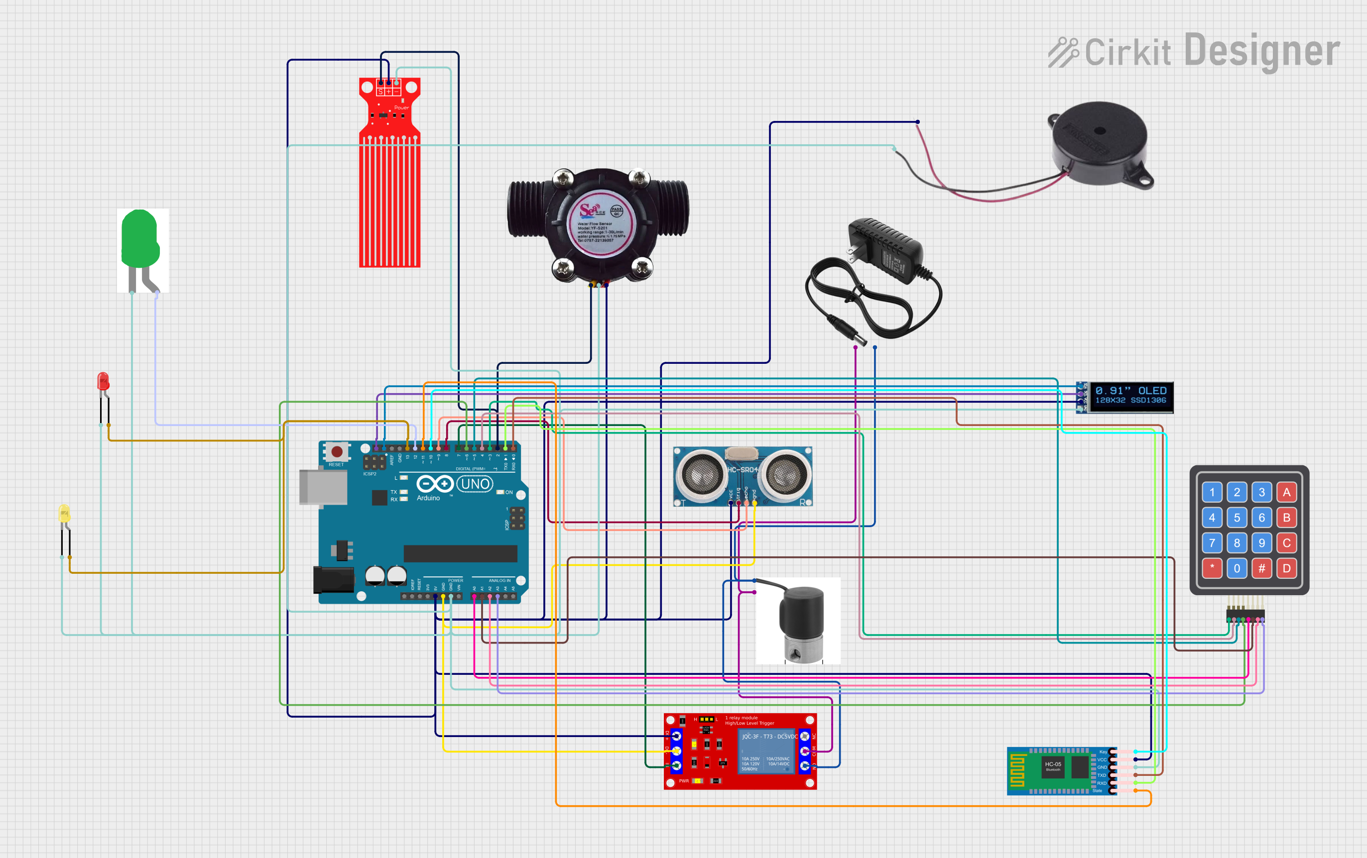
Circuit Documentation
Summary
This circuit is designed to control a solenoid valve based on water flow and water level sensors. It uses an Arduino UNO as the main microcontroller, interfacing with various sensors and modules including a Bluetooth module, an OLED display, a relay module, and LEDs for status indication. The system can receive desired water volume via Bluetooth and display real-time data on the OLED screen. The solenoid valve is controlled based on the water flow and level readings.
Component List
HC-05 Bluetooth Module
- Description: Bluetooth module for wireless communication.
- Pins: Key, VCC, GND, TXD, RXD, State
Solenoid Valve 12V
- Description: Electromechanical valve controlled by a 12V power supply.
- Pins: GND, 12V
1 Channel 5V Relay Module
- Description: Relay module to control high voltage devices.
- Pins: VCC+, VCC- (GND), IN, N.O., COM, N.C.
12V Power Supply
- Description: Power supply providing 12V DC.
- Pins: +, -
OLED Display 128x32
- Description: OLED display for visual output.
- Pins: SDA, SCL, VCC, GND
4x4 Keypad (Simulator)
- Description: Keypad for user input.
- Pins: R1, C4, R2, C2, R3, R4, C1, C3
Ultrasonic Sensor
- Description: Sensor for measuring distance.
- Pins: +VCC, Trigger, Echo, GND
Water Flow Sensor
- Description: Sensor for measuring water flow rate.
- Pins: Signal, Vcc, GND
LED: Two Pin (Red)
- Description: Red LED for status indication.
- Pins: Cathode, Anode
LED: Two Pin (Green)
- Description: Green LED for status indication.
- Pins: Cathode, Anode
LED: Two Pin (Yellow)
- Description: Yellow LED for status indication.
- Pins: Cathode, Anode
Water Level Sensor
- Description: Sensor for measuring water level.
- Pins: SIG, VCC, GND
Buzzer
- Description: Buzzer for audible alerts.
- Pins: Positive, Negative
Arduino UNO
- Description: Main microcontroller.
- Pins: UNUSED, IOREF, Reset, 3.3V, 5V, GND, Vin, A0, A1, A2, A3, A4, A5, SCL, SDA, AREF, D13, D12, D11, D10, D9, D8, D7, D6, D5, D4, D3, D2, D1, D0
Wiring Details
HC-05 Bluetooth Module
- VCC to Arduino UNO 5V
- GND to Arduino UNO GND
- TXD to Arduino UNO D0
- RXD to Arduino UNO D1
- State to Arduino UNO D11
- Key to Arduino UNO D10
Solenoid Valve 12V
- GND to 1 Channel 5V Relay Module N.O.
- 12V to 1 Channel 5V Relay Module COM
1 Channel 5V Relay Module
- VCC+ to Arduino UNO 5V
- VCC- (GND) to Arduino UNO GND
- IN to Arduino UNO D7
- N.O. to Solenoid Valve GND
- COM to Solenoid Valve 12V
12V Power Supply
- + to 1 Channel 5V Relay Module COM
- - to 1 Channel 5V Relay Module N.O.
OLED Display 128x32
- VCC to Arduino UNO 5V
- GND to Arduino UNO GND
- SCL to Arduino UNO SCL
- SDA to Arduino UNO SDA
4x4 Keypad (Simulator)
- C1 to Arduino UNO A0
- C2 to Arduino UNO A1
- C3 to Arduino UNO A2
- C4 to Arduino UNO A3
- R1 to Arduino UNO D3
- R2 to Arduino UNO D4
- R3 to Arduino UNO D5
- R4 to Arduino UNO D6
Ultrasonic Sensor
- +VCC to Arduino UNO 5V
- GND to Arduino UNO GND
- Trigger to Arduino UNO D8
- Echo to Arduino UNO D9
Water Flow Sensor
- Vcc to Arduino UNO 5V
- GND to Arduino UNO GND
- Signal to Arduino UNO D2
LED: Two Pin (Red)
- Anode to Arduino UNO D13
- Cathode to Arduino UNO GND
LED: Two Pin (Green)
- Anode to Arduino UNO D12
- Cathode to Arduino UNO GND
LED: Two Pin (Yellow)
- Anode to Arduino UNO D13
- Cathode to Arduino UNO GND
Water Level Sensor
- VCC to Arduino UNO 5V
- GND to Arduino UNO GND
- SIG to Arduino UNO D2
Buzzer
- Positive to Arduino UNO 5V
- Negative to Arduino UNO GND
Code Documentation
#include <SoftwareSerial.h>
#include <Wire.h>
#include <Adafruit_GFX.h>
#include <Adafruit_SSD1306.h>

#define SCREEN_WIDTH 128
#define SCREEN_HEIGHT 32
#define OLED_RESET    -1
Adafruit_SSD1306 display(SCREEN_WIDTH, SCREEN_HEIGHT, &Wire, OLED_RESET);

SoftwareSerial BTSerial(0, 1); // RX, TX

const int relayPin = 7;
const int waterLevelSensorPin = 2;
const int flowSensorPin = 2;
const int buzzerPin = 8;
const int redLEDPin = 13;
const int yellowLEDPin = 12;
const int greenLEDPin = 11;

volatile int flowPulseCount = 0;
float flowRate = 0.0;
float totalLitres = 0.0;
float desiredLitres = 0.0;

void setup() {
  pinMode(relayPin, OUTPUT);
  pinMode(waterLevelSensorPin, INPUT);
  pinMode(flowSensorPin, INPUT);
  pinMode(buzzerPin, OUTPUT);
  pinMode(redLEDPin, OUTPUT);
  pinMode(yellowLEDPin, OUTPUT);
  pinMode(greenLEDPin, OUTPUT);

  attachInterrupt(digitalPinToInterrupt(flowSensorPin), flowPulseCounter, RISING);

  BTSerial.begin(9600);
  Serial.begin(9600);

  display.begin(SSD1306_SWITCHCAPVCC, 0x3C);
  display.display();
  delay(2000);
  display.clearDisplay();
}

void loop() {
  if (BTSerial.available()) {
    desiredLitres = BTSerial.parseFloat();
  }

  flowRate = (flowPulseCount / 7.5); // Example conversion factor
  totalLitres += (flowRate / 60);

  display.clearDisplay();
  display.setTextSize(1);
  display.setTextColor(SSD1306_WHITE);
  display.setCursor(0, 0);
  display.print("Flow Rate: ");
  display.print(flowRate);
  display.print(" L/min");
  display.setCursor(0, 10);
  display.print("Total: ");
  display.print(totalLitres);
  display.print(" L");
  display.display();

  if (totalLitres >= desiredLitres) {
    digitalWrite(relayPin, LOW);
    digitalWrite(buzzerPin, HIGH);
  } else {
    digitalWrite(relayPin, HIGH);
    digitalWrite(buzzerPin, LOW);
  }

  // LED Indicators for Water Level
  if (totalLitres < desiredLitres * 0.33) {
    digitalWrite(redLEDPin, HIGH);
    digitalWrite(yellowLEDPin, LOW);
    digitalWrite(greenLEDPin, LOW);
  } else if (totalLitres < desiredLitres * 0.66) {
    digitalWrite(redLEDPin, LOW);
    digitalWrite(yellowLEDPin, HIGH);
    digitalWrite(greenLEDPin, LOW);
  } else {
    digitalWrite(redLEDPin, LOW);
    digitalWrite(yellow