Arduino Mega-Controlled Stepper Motors with IR Communication and Position Limiting
Circuit Documentation
Summary
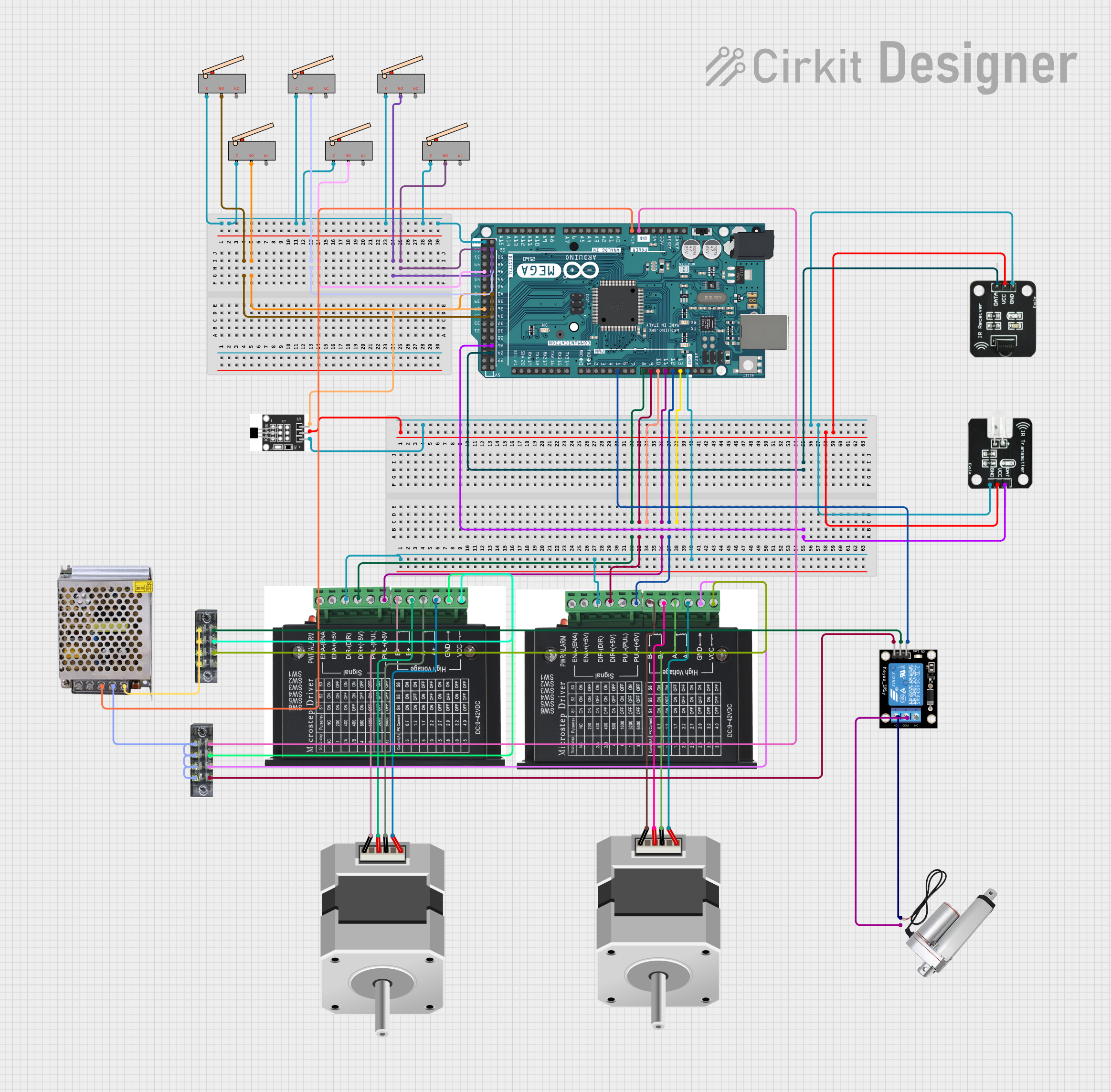
This circuit is designed to control a system that includes two bipolar stepper motors, multiple limit switches, a hall sensor, an IR transmitter and receiver pair, and a linear actuator. The central control unit for this system is an Arduino Mega 2560, which interfaces with the various components to manage their operation. The stepper motors are driven by dedicated stepper drivers, and the limit switches provide positional feedback. The hall sensor is used for detecting magnetic fields, while the IR components enable wireless data transmission. A relay module is used to control the power to the linear actuator. The entire system is powered by a 12V 5A power supply.
Component List
- Stepper Motor (Bipolar): A type of motor that is driven by electric pulses and capable of precise position control.
- Stepper Driver: An electronic device that drives the stepper motor by converting pulse signals into motor motion.
- Limit Switch: A switch that is actuated by the motion of a machine part or presence of an object, used for control or safety purposes.
- Hall Sensor: A transducer that varies its output voltage in response to a magnetic field.
- Arduino Mega 2560: A microcontroller board based on the ATmega2560, with numerous I/O pins for interfacing with various components.
- IR Receiver: A component that receives IR signals and converts them into electrical signals.
- IR Transmitter: A component that emits infrared light to transmit data wirelessly.
- Power Supply 12V 5A: Provides the necessary power to the circuit components.
- Terminal Block: A type of electrical connector where wires are clamped down to the metal part by a screw.
- Linear Actuator: A device that creates motion in a straight line using an external power source.
- Relay Module 1 Channel: An electrically operated switch that allows you to control a high power circuit with a low power signal.
Wiring Details
Stepper Motors
- Stepper Motor 1: Connected to the first stepper driver (A+, A-, B+, B-).
- Stepper Motor 2: Connected to the second stepper driver (A+, A-, B+, B-).
Stepper Drivers
- Stepper Driver 1: Control inputs (DIR+, PUL+) connected to Arduino Mega (D8 PWM, D11 PWM), power inputs (VCC, GND) connected to the power supply via terminal block.
- Stepper Driver 2: Control inputs (DIR+, PUL+) connected to Arduino Mega (D9 PWM, D12 PWM), power inputs (VCC, GND) connected to the power supply via terminal block.
Limit Switches
- Limit Switches: Connected to various digital pins on the Arduino Mega for positional feedback.
Hall Sensor
- Hall Sensor: Power (VCC, GND) connected to the power supply, signal (S) connected to Arduino Mega (D37).
IR Components
- IR Receiver: Data pin connected to Arduino Mega (D24), power (VCC, GND) connected to the power supply.
- IR Transmitter: Data pin connected to Arduino Mega (D26), power (VCC, GND) connected to the power supply.
Power Supply
- Power Supply 12V 5A: Provides power to the circuit, with connections to the terminal blocks for distribution to components.
Terminal Blocks
- Terminal Block 1: Used for ground connections.
- Terminal Block 2: Used for VCC connections.
Linear Actuator
- Linear Actuator: Connected to the relay module (NO, COM) for controlled actuation.
Relay Module
- Relay Module 1 Channel: Signal (S) connected to Arduino Mega (D5 PWM), power (VCC, GND) connected to the power supply via terminal block, controls the linear actuator.
Documented Code
void setup() {
  // put your setup code here, to run once:

}

void loop() {
  // put your main code here, to run repeatedly:

}
The provided code is a template for the Arduino Mega 2560 and does not contain any functional code. The setup() function is intended for initialization code that runs once, while the loop() function contains code that runs repeatedly, forming the main logic of the microcontroller's program. Actual implementation details would be added to these functions based on the specific requirements of the circuit's operation.