Cirkit Designer
Your all-in-one circuit design IDE
Home /
Project Documentation
Arduino UNO Controlled Smart Home System with Bluetooth and Relay Shield
Circuit Documentation
Summary
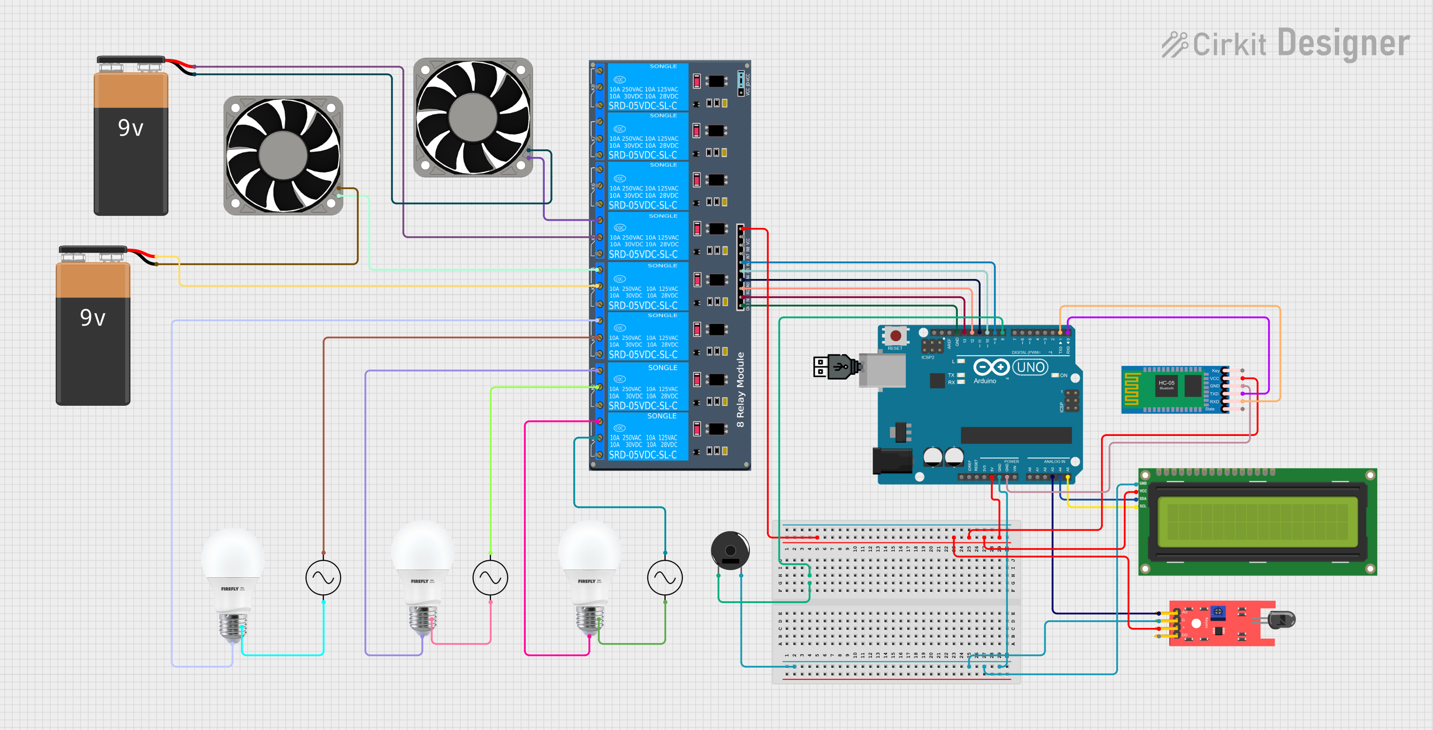
This circuit integrates various components controlled by an Arduino UNO microcontroller. It includes a Bluetooth module for wireless communication, a relay shield for controlling high-power devices, a flame sensor for detecting fire or flame presence, an I2C LCD screen for display, a piezo buzzer for audio alerts, and multiple power supplies for different voltage requirements. The circuit is designed to monitor environmental conditions and control devices accordingly.
Component List
Arduino UNO
- Microcontroller board based on the ATmega328P
- It has 14 digital input/output pins, 6 analog inputs, a 16 MHz quartz crystal, a USB connection, a power jack, an ICSP header, and a reset button.
HC-05 Bluetooth Module
- Wireless communication module that allows for Bluetooth connectivity
- It has pins for key, power (VCC), transmit (TXD), receive (RXD), state, and ground (GND).
8-Channel 5V Relay Shield
- A module that allows an Arduino board to control high power loads
- It has 8 channels with individual inputs and a common VCC and GND.
KY-026 Flame Sensor
- A sensor module designed to detect fire or flame presence
- It has analog output (A0), digital output (D0), power (VCC), and ground (GND) pins.
BULB
- An electric light source
- It has two terminals: positive (+) and negative (-).
AC Supply
- Provides alternating current power
- It has two terminals: positive (+ve) and negative (-ve).
40 Fan 12V
- A 12V fan for cooling purposes
- It has two terminals: positive (+12V) and negative (-12V).
9V Battery
- A power source providing 9 volts of DC power
- It has two terminals: positive (+) and negative (-).
I2C LCD 16x2 Screen
- A liquid crystal display capable of showing 16 characters per 2 lines
- It has pins for I2C communication (SCL, SDA), power (VCC, GND), and other control pins.
Piezo Buzzer
- An electronic device that produces sound
- It has two pins: pin 1 and pin 2.
USB Power
- A power source that provides power through a USB interface
- It has two terminals: positive (+) and negative (-).
Wiring Details
Arduino UNO
- 5V: Connected to VCC of HC-05, Relay Shield, Flame Sensor, and I2C LCD Screen
- GND: Connected to GND of Flame Sensor, I2C LCD Screen, Piezo Buzzer, HC-05, and Relay Shield
- A3: Connected to A0 of Flame Sensor
- A4: Connected to SDA of I2C LCD Screen
- A5: Connected to SCL of I2C LCD Screen
- D13: Connected to IN1 of Relay Shield
- D12: Connected to IN2 of Relay Shield
- D11: Connected to IN3 of Relay Shield
- D10: Connected to IN4 of Relay Shield
- D9: Connected to IN5 of Relay Shield
- D8: Connected to pin 1 of Piezo Buzzer
- D1: Connected to RXD of HC-05
- D0: Connected to TXD of HC-05
HC-05 Bluetooth Module
- VCC: Powered by 5V from Arduino UNO
- GND: Connected to GND on Arduino UNO
- TXD: Connected to D0 on Arduino UNO
- RXD: Connected to D1 on Arduino UNO
8-Channel 5V Relay Shield
- VCC: Powered by 5V from Arduino UNO
- GND: Connected to GND on Arduino UNO
- IN1 - IN5: Controlled by D13 - D9 on Arduino UNO
- K2-On: Connected to + of Bulb
- K1-On: Connected to + of another Bulb
- K1-Off, K2-Off: Connected to +ve of AC Supplies
- K3-On, K4-On: Connected to + of Bulb and +12V of 40 Fan 12V respectively
- K3-Off, K4-Off: Connected to +ve of AC Supply and + of 9V Battery respectively
- K5-On: Connected to +12V of another 40 Fan 12V
- K5-Off: Connected to + of another 9V Battery
KY-026 Flame Sensor
- VCC: Powered by 5V from Arduino UNO
- GND: Connected to GND on Arduino UNO
- A0: Connected to A3 on Arduino UNO
I2C LCD 16x2 Screen
- VCC (5V): Powered by 5V from Arduino UNO
- GND: Connected to GND on Arduino UNO
- SDA: Connected to A4 on Arduino UNO
- SCL: Connected to A5 on Arduino UNO
Piezo Buzzer
- Pin 1: Controlled by D8 on Arduino UNO
- Pin 2: Connected to GND on Arduino UNO
BULB
- +: Connected to K2-On, K1-On, and K3-On on Relay Shield
- -: Connected to -ve of AC Supplies
AC Supply
- +ve: Connected to K1-Off, K2-Off, K3-Off on Relay Shield
- -ve: Connected to - of Bulbs
40 Fan 12V
- +12V: Controlled by K4-On and K5-On on Relay Shield
- -12V: Connected to - of 9V Batteries
9V Battery
- +: Connected to K4-Off and K5-Off on Relay Shield
- -: Connected to -12V of 40 Fans 12V
Documented Code
Arduino UNO - sketch.ino
void setup() {
  // put your setup code here, to run once:

}

void loop() {
  // put your main code here, to run repeatedly:

}
Arduino UNO - documentation.txt
(No additional documentation provided)