
Arduino Mega 2560 and ESP32-CAM Based Smart Sensor System with I2C LCD Display
View and Edit Project In Cirkit Designer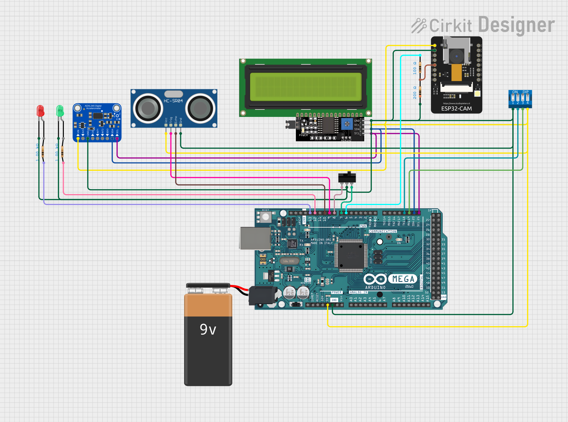
Circuit Documentation
Summary
This document provides a detailed overview of a circuit that integrates various components including an ESP32-CAM, an Arduino Mega 2560, an LCD Display, an ultrasonic sensor, a toggle switch, a DIP switch, LEDs, resistors, and a 9V battery. The circuit is designed to perform multiple functions, including sensor data acquisition, display output, and user interaction through switches.
Component List
Adafruit ADXL345
- Description: 3-axis accelerometer
- Pins: VIN, 3.3V, GND, CS, INT1, INT2, SDO/ADDR, SDA/SDIO, SCL
ESP32 - CAM
- Description: Wi-Fi and Bluetooth-enabled microcontroller with a camera
- Pins: 5V, GND, IO12, IO13, IO15, IO14, IO2, IO4, VOT, VOR, VCC, IO0, IO16, 3V3
LCD Display 16x4 I2C
- Description: 16x4 character LCD display with I2C interface
- Pins: SCL, SDA, VCC, GND
HC-SR04 Ultrasonic Sensor
- Description: Ultrasonic distance sensor
- Pins: VCC, TRIG, ECHO, GND
Toggle Switch
- Description: Single-pole double-throw (SPDT) toggle switch
- Pins: L1, COM, L2
9V Battery
- Description: Power source
- Pins: -, +
DIP Switch 4 Position
- Description: 4-position DIP switch
- Pins: 1, 2, 3, 4, 5, 6, 7, 8
Arduino Mega 2560
- Description: Microcontroller board based on the ATmega2560
- Pins: IOREF, RESET, 3V3, 5V, GND, VIN, A0-A15, D0-D53, AREF, SDA, SCL
LED: Two Pin (red)
- Description: Red LED
- Pins: cathode, anode
LED: Two Pin (green)
- Description: Green LED
- Pins: cathode, anode
Resistor (1000 Ohms)
- Description: Resistor with 1000 Ohms resistance
- Pins: pin1, pin2
Resistor (100 Ohms)
- Description: Resistor with 100 Ohms resistance
- Pins: pin1, pin2
Resistor (200 Ohms)
- Description: Resistor with 200 Ohms resistance
- Pins: pin1, pin2
Wiring Details
Adafruit ADXL345
- VIN: Connected to 5V (ESP32 - CAM, LCD Display, HC-SR04, Arduino Mega 2560, DIP Switch)
- GND: Connected to GND (ESP32 - CAM, Resistor, LCD Display, Toggle Switch, HC-SR04, Red LED, Green LED, Arduino Mega 2560, DIP Switch)
- SDA/SDIO: Connected to SDA (LCD Display, Arduino Mega 2560)
- SCL: Connected to SCL (LCD Display, Arduino Mega 2560)
ESP32 - CAM
- 5V: Connected to 5V (LCD Display, HC-SR04, Arduino Mega 2560, DIP Switch, Adafruit ADXL345)
- GND: Connected to GND (Resistor, LCD Display, Toggle Switch, HC-SR04, Red LED, Green LED, Arduino Mega 2560, DIP Switch)
- IO15: Connected to pin1 (Resistor)
- IO12, IO13, IO14, IO2, IO4, VOT, VOR, VCC, IO0, IO16, 3V3: Not connected
LCD Display 16x4 I2C
- VCC: Connected to 5V (ESP32 - CAM, HC-SR04, Arduino Mega 2560, DIP Switch, Adafruit ADXL345)
- GND: Connected to GND (ESP32 - CAM, Resistor, Toggle Switch, HC-SR04, Red LED, Green LED, Arduino Mega 2560, DIP Switch, Adafruit ADXL345)
- SDA: Connected to SDA (Arduino Mega 2560, Adafruit ADXL345)
- SCL: Connected to SCL (Arduino Mega 2560, Adafruit ADXL345)
HC-SR04 Ultrasonic Sensor
- VCC: Connected to 5V (ESP32 - CAM, LCD Display, Arduino Mega 2560, DIP Switch, Adafruit ADXL345)
- GND: Connected to GND (ESP32 - CAM, Resistor, LCD Display, Toggle Switch, Red LED, Green LED, Arduino Mega 2560, DIP Switch, Adafruit ADXL345)
- TRIG: Connected to D9 PWM (Arduino Mega 2560)
- ECHO: Connected to D10 PWM (Arduino Mega 2560)
Toggle Switch
- COM: Connected to GND (ESP32 - CAM, Resistor, LCD Display, HC-SR04, Red LED, Green LED, Arduino Mega 2560, DIP Switch, Adafruit ADXL345)
- L1: Connected to D8 PWM (Arduino Mega 2560)
- L2: Connected to D7 PWM (Arduino Mega 2560)
9V Battery
- -: Not connected
- +: Not connected
DIP Switch 4 Position
- 1: Connected to GND (ESP32 - CAM, Resistor, LCD Display, Toggle Switch, HC-SR04, Red LED, Green LED, Arduino Mega 2560, Adafruit ADXL345)
- 2: Connected to D18/TX1 (Arduino Mega 2560)
- 3: Connected to D19/RX1 (Arduino Mega 2560)
- 4: Connected to 5V (ESP32 - CAM, LCD Display, HC-SR04, Arduino Mega 2560, Adafruit ADXL345)
Arduino Mega 2560
- 5V: Connected to 5V (ESP32 - CAM, LCD Display, HC-SR04, DIP Switch, Adafruit ADXL345)
- GND: Connected to GND (ESP32 - CAM, Resistor, LCD Display, Toggle Switch, HC-SR04, Red LED, Green LED, DIP Switch, Adafruit ADXL345)
- D9 PWM: Connected to TRIG (HC-SR04)
- D10 PWM: Connected to ECHO (HC-SR04)
- D8 PWM: Connected to L1 (Toggle Switch)
- D7 PWM: Connected to L2 (Toggle Switch)
- D18/TX1: Connected to 2 (DIP Switch)
- D19/RX1: Connected to 3 (DIP Switch)
- D6 PWM: Connected to pin2 (Resistor)
- D12 PWM: Connected to pin1 (Resistor)
- D13 PWM: Connected to pin1 (Resistor)
- SDA: Connected to SDA (LCD Display, Adafruit ADXL345)
- SCL: Connected to SCL (LCD Display, Adafruit ADXL345)
LED: Two Pin (red)
- cathode: Connected to GND (ESP32 - CAM, Resistor, LCD Display, Toggle Switch, HC-SR04, Green LED, Arduino Mega 2560, DIP Switch, Adafruit ADXL345)
- anode: Not connected
LED: Two Pin (green)
- cathode: Connected to GND (ESP32 - CAM, Resistor, LCD Display, Toggle Switch, HC-SR04, Red LED, Arduino Mega 2560, DIP Switch, Adafruit ADXL345)
- anode: Not connected
Resistor (1000 Ohms)
- pin1: Connected to D13 PWM (Arduino Mega 2560)
- pin2: Not connected
Resistor (100 Ohms)
- pin1: Connected to IO15 (ESP32 - CAM)
- pin2: Connected to D6 PWM (Arduino Mega 2560)
Resistor (200 Ohms)
- pin1: Connected to GND (ESP32 - CAM, LCD Display, Toggle Switch, HC-SR04, Red LED, Green LED, Arduino Mega 2560, DIP Switch, Adafruit ADXL345)
- pin2: Not connected
Documented Code
Arduino Mega 2560 Code (sketch.ino)
void setup() {
  // put your setup code here, to run once:

}

void loop() {
  // put your main code here, to run repeatedly:

}
Additional Documentation (documentation.txt)