
Wi-Fi Controlled Smart Light with ESP8266 and Voltage Sensor
View and Edit Project In Cirkit Designer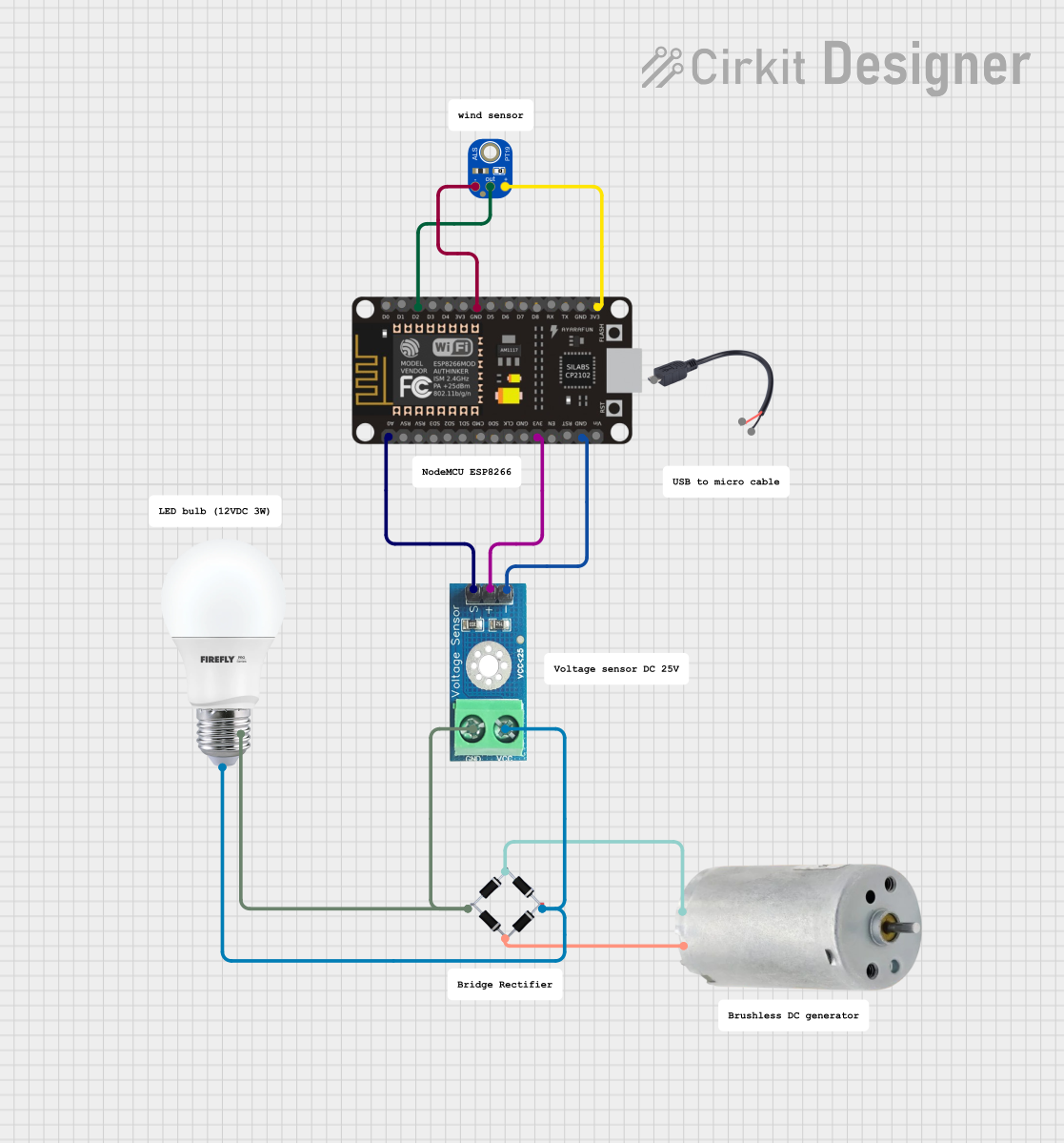
Circuit Documentation
Summary
This document provides a detailed overview of a circuit that includes an ESP8266 NodeMCU, a voltage sensor, a light sensor, a DC generator, a bridge rectifier, and a bulb. The circuit is designed to measure voltage and light intensity, and it includes a power generation and rectification system.
Component List
ESP8266 NodeMCU
- Description: A low-cost Wi-Fi microcontroller with multiple GPIO pins.
- Pins: D0, D1, D2, D3, D4, 3V3, GND, D5, D6, D7, D8, RX, TX, A0, RSV, SD3, SD2, SD1, CMD, SD0, CLK, EN, RST, VIN
Voltage Sensor DC 25V
- Description: A sensor to measure DC voltage up to 25V.
- Pins: +, -, output, gnd, vcc
ALSPT19315C
- Description: A light sensor to measure ambient light intensity.
- Pins: GND, OUT, VCC
Micro USB to Cable (2 Pin)
- Description: A micro USB to 2-pin cable for power supply.
- Pins: Micro USB, +, -
DC Generator
- Description: A generator to produce DC voltage.
- Pins: + PIN, - PIN
Bridge Rectifier
- Description: A rectifier to convert AC to DC.
- Pins: Source_in-, source_out-, source_out+, source_in+
Bulb
- Description: A simple bulb to indicate power.
- Pins: +, -
Wiring Details
ESP8266 NodeMCU
- D2 is connected to OUT of the ALSPT19315C light sensor.
- GND is connected to GND of the ALSPT19315C light sensor.
- 3V3 is connected to VCC of the ALSPT19315C light sensor.
- A0 is connected to output of the Voltage Sensor DC 25V.
- 3V3 is connected to + of the Voltage Sensor DC 25V.
- GND is connected to - of the Voltage Sensor DC 25V.
Voltage Sensor DC 25V
- output is connected to A0 of the ESP8266 NodeMCU.
- + is connected to 3V3 of the ESP8266 NodeMCU.
- - is connected to GND of the ESP8266 NodeMCU.
- gnd is connected to - of the Bulb and source_out- of the Bridge Rectifier.
- vcc is connected to + of the Bulb and source_out+ of the Bridge Rectifier.
ALSPT19315C
- OUT is connected to D2 of the ESP8266 NodeMCU.
- GND is connected to GND of the ESP8266 NodeMCU.
- VCC is connected to 3V3 of the ESP8266 NodeMCU.
DC Generator
- + PIN is connected to source_in+ of the Bridge Rectifier.
- - PIN is connected to Source_in- of the Bridge Rectifier.
Bridge Rectifier
- source_in+ is connected to + PIN of the DC Generator.
- Source_in- is connected to - PIN of the DC Generator.
- source_out- is connected to gnd of the Voltage Sensor DC 25V and - of the Bulb.
- source_out+ is connected to vcc of the Voltage Sensor DC 25V and + of the Bulb.
Bulb
- - is connected to gnd of the Voltage Sensor DC 25V and source_out- of the Bridge Rectifier.
- + is connected to vcc of the Voltage Sensor DC 25V and source_out+ of the Bridge Rectifier.
Code
No code is provided for this circuit.