
Circuit Documentation
Summary
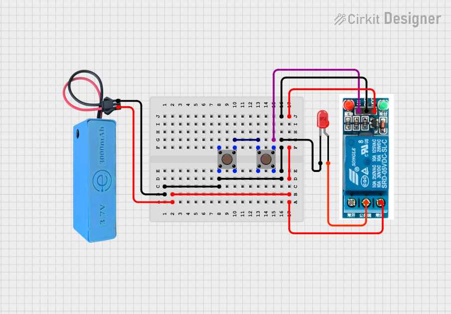
This circuit consists of a power source, a red LED, two pushbuttons, and a 5V relay. The circuit is designed to control the LED and relay using the pushbuttons. The power source provides the necessary voltage to the components, and the pushbuttons are used to control the state of the LED and relay.
Component List
MAHIR 1.mini
- Description: Power source providing 3.7V and GND.
- Pins: GND, 3.7V
LED: Two Pin (red)
- Description: A red LED with two pins: cathode and anode.
- Pins: Cathode, Anode
Pushbutton
- Description: A pushbutton with four pins.
- Pins: Pin 1 (in), Pin 2 (in), Pin 3 (out), Pin 4 (out)
Pushbutton
- Description: A pushbutton with four pins.
- Pins: Pin 1 (in), Pin 2 (in), Pin 3 (out), Pin 4 (out)
5V Relay
- Description: A relay with six pins.
- Pins: Normally Open, Common terminal, Normally Closed, In, GND, VCC
Wiring Details
MAHIR 1.mini
GND is connected to:
- Pushbutton Pin 2 (in)
- LED Cathode
- 5V Relay GND
3.7V is connected to:
- 5V Relay Normally Closed
- 5V Relay VCC
LED: Two Pin (red)
Cathode is connected to:
- Pushbutton Pin 2 (in)
- MAHIR 1.mini GND
- 5V Relay GND
Anode is connected to:
- 5V Relay Common terminal
Pushbutton (1)
Pin 1 (in) is connected to:
- Pushbutton (2) Pin 3 (out)
Pin 2 (in) is connected to:
- LED Cathode
- MAHIR 1.mini GND
- 5V Relay GND
Pin 3 (out) is connected to:
- Pushbutton (2) Pin 1 (in)
Pin 4 (out) is not connected.
Pushbutton (2)
Pin 1 (in) is connected to:
- Pushbutton (1) Pin 3 (out)
Pin 2 (in) is not connected.
Pin 3 (out) is connected to:
- Pushbutton (1) Pin 1 (in)
- 5V Relay In
Pin 4 (out) is not connected.
5V Relay
Normally Open is not connected.
Common terminal is connected to:
- LED Anode
Normally Closed is connected to:
- MAHIR 1.mini 3.7V
In is connected to:
- Pushbutton (2) Pin 3 (out)
GND is connected to:
- MAHIR 1.mini GND
- LED Cathode
VCC is connected to:
- MAHIR 1.mini 3.7V
Code
There is no code provided for this circuit.